hospadar
Member
Just replaced the (mostly dead) selenium cell in a Contax IIIa meter with silicon and things are looking good! Just wanted to document the process for anyone else who might need to.
The cell i used is an IXOLAR KX0B25-14X1TF - it’s 23x8x1.2mm which is small enough to fit in where the original selenium cell went. The open-circuit voltage is rated ~.6v which is similar to a selenium cell (higher voltage cells are available and would probably work but aren’t necessary). The original selenium cell is 1.2mm thick and a bit bigger. This cell is a monocrystalline cell which puts out a lot more power than the typical amorphous cells found in solar powered calculators. I did a a similar replacement job on the meter in a mamiya 16 ee deluxe and initially attempted to use an amorphous cells found harvested from a thrift store calculator, but that cell didn’t put out enough power. Not sure if a monocrystalline cell is strictly a requirement when replacing selenium cells (different meter movements might accommodate a weaker cell) but it’s only $3 for the nicest cell you can buy so why not.
First thing is to remove the positive cell contact, it’s the creased plate behind the cell. If you desolder the wire that connects it to the pcb you can pull it right out.
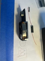
With the electrode removed the front of the meter should look like so.
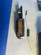
A little circuit diagram to help identify the 4 pins on the pcb. Clockwise from the top right: positive cell, resistor, meter positive, resistor. In this photo I’ve already desoldered the fixed resistor from the two resistor contacts. Apparently some late-model IIIa meters come with a trimpot factory installed. If yours does, great, but if not, you’ll need to remove the resistor and replace it with a trimpot. My fixed resistor measured about 5kohm and i installed a 10kohm trimmer.
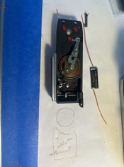
The new trimmer soldered into place as well as the cell wiring. The red wire on top is positive cell contact. The two resistor pins on the pcb should be connected to the center contact on the trimmer (the wiper) and one of the side contacts. The negative side of the cell needs to be connected to the chassis some way, out of the factory there are little tabs that are just squeezed onto the top plate, I soldered the negative wire to the mount point of the little brass spring that grounds the meter movement. Any secure electrical connection to any part of the chassis would be fine.
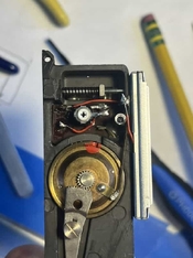
The cell in position it’s not attached by anything other than the wires. I put a small piece of 1mm light seal foam behind it so that when the plastic lens is slid into place it’ll be firmly nestled in there and won’t jiggle around.

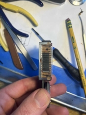
The lens slid back into place over the cell.
Once you’ve got all the electrical connections hooked up, reattach the meter wheel (that goes around the rewind knob) and calibrate the meter against another meter you trust using the trimmer. I use evenly illuminated walls and frosted glass windows for calibration usually. My trimmer ended up around 2.1kohm after calibration.
Note that the silicon cell does not have the same spectral response as the original selenium cell, it responds much more strongly to red whereas the selenium cell is much flatter across the visual spectrum. In practice, for typical subjects i think this is probably fine, but you could slide in a blue or cyan filter between the cell and the lens to try and balance things out. Anecdotally in normal outdoor scenes the calibrated meter compares very favorably to a gossen SBC meter i have but presumably you’d see some underexposure of very blue or green subjects.
I’m honestly not sure if the linearity of the silicon cell is the same as the selenium, but after calibration the meter reads within a half stop of my reference meter in bright sun and a dimly lit room, so I’m pretty satisfied. Realistically if this meter reads within a stop of accurate between ev 16 and ev 8 it’ll get the job done just fine (and it’s a heluva lot better than the totally dead meter it used to be!)
The cell i used is an IXOLAR KX0B25-14X1TF - it’s 23x8x1.2mm which is small enough to fit in where the original selenium cell went. The open-circuit voltage is rated ~.6v which is similar to a selenium cell (higher voltage cells are available and would probably work but aren’t necessary). The original selenium cell is 1.2mm thick and a bit bigger. This cell is a monocrystalline cell which puts out a lot more power than the typical amorphous cells found in solar powered calculators. I did a a similar replacement job on the meter in a mamiya 16 ee deluxe and initially attempted to use an amorphous cells found harvested from a thrift store calculator, but that cell didn’t put out enough power. Not sure if a monocrystalline cell is strictly a requirement when replacing selenium cells (different meter movements might accommodate a weaker cell) but it’s only $3 for the nicest cell you can buy so why not.
First thing is to remove the positive cell contact, it’s the creased plate behind the cell. If you desolder the wire that connects it to the pcb you can pull it right out.

With the electrode removed the front of the meter should look like so.

A little circuit diagram to help identify the 4 pins on the pcb. Clockwise from the top right: positive cell, resistor, meter positive, resistor. In this photo I’ve already desoldered the fixed resistor from the two resistor contacts. Apparently some late-model IIIa meters come with a trimpot factory installed. If yours does, great, but if not, you’ll need to remove the resistor and replace it with a trimpot. My fixed resistor measured about 5kohm and i installed a 10kohm trimmer.

The new trimmer soldered into place as well as the cell wiring. The red wire on top is positive cell contact. The two resistor pins on the pcb should be connected to the center contact on the trimmer (the wiper) and one of the side contacts. The negative side of the cell needs to be connected to the chassis some way, out of the factory there are little tabs that are just squeezed onto the top plate, I soldered the negative wire to the mount point of the little brass spring that grounds the meter movement. Any secure electrical connection to any part of the chassis would be fine.

The cell in position it’s not attached by anything other than the wires. I put a small piece of 1mm light seal foam behind it so that when the plastic lens is slid into place it’ll be firmly nestled in there and won’t jiggle around.

The lens slid back into place over the cell.

Once you’ve got all the electrical connections hooked up, reattach the meter wheel (that goes around the rewind knob) and calibrate the meter against another meter you trust using the trimmer. I use evenly illuminated walls and frosted glass windows for calibration usually. My trimmer ended up around 2.1kohm after calibration.
Note that the silicon cell does not have the same spectral response as the original selenium cell, it responds much more strongly to red whereas the selenium cell is much flatter across the visual spectrum. In practice, for typical subjects i think this is probably fine, but you could slide in a blue or cyan filter between the cell and the lens to try and balance things out. Anecdotally in normal outdoor scenes the calibrated meter compares very favorably to a gossen SBC meter i have but presumably you’d see some underexposure of very blue or green subjects.
I’m honestly not sure if the linearity of the silicon cell is the same as the selenium, but after calibration the meter reads within a half stop of my reference meter in bright sun and a dimly lit room, so I’m pretty satisfied. Realistically if this meter reads within a stop of accurate between ev 16 and ev 8 it’ll get the job done just fine (and it’s a heluva lot better than the totally dead meter it used to be!)


