Designing a new affordable production-ready Autocollimator

totocalcio

A
totocalcio

  • 3
  • 0
  • 42
Untitled

A
Untitled

  • 5
  • 2
  • 98
Jerome Leaves

H
Jerome Leaves

  • 3
  • 0
  • 70
Jerome

H
Jerome

  • 2
  • 0
  • 70
Sedona Tree

H
Sedona Tree

  • 1
  • 0
  • 75

Recent Classifieds

Forum statistics

Threads
197,438
Messages
2,758,998
Members
99,500
Latest member
noiva
Recent bookmarks
1

Reveni-matt

Member
Joined
Jul 24, 2024
Messages
47
Location
Canada
Format
35mm
Hi guys,

Matt from Reveni Labs here. I'm working on designing an affordable autocollimator to release in 2025. Trouble is, I have no hands-on experience with a real autocollimator so I'm piecing things together bit by bit just from what I'm reading. I'm working to separate the "gotta haves" from the "nice to haves" and the "don't needs" so keep the cost down and it would be great to get the opinions of some experienced users. The aim is to get the MSRP near $500 USD.

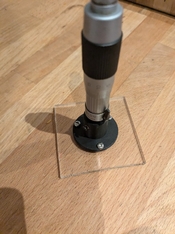
I built a 3D printed prototype to get started, and it works quite well, I think. I can see the target (a microscope eyepiece reticle) very well when reflected off a first-surface mirror mounted at the inner film rails. It uses a 62mm D 300mm F telescope objective.

2024-10-29 17.16.48 (Large).jpg
2024-11-08 16.32.51 (Large).jpg


I'm moving on to a metal prototype design, with a 32mmD 372.4mm F objective. Here's where I'm working to determine the "gotta haves" from the "nice to haves" and "don't needs".

If I may refer to this drawing:

Autocollimator c-6005 Pearl National Camera.png


Clear gotta-haves:
1. Lamp - a nice bright LED will suffice, variable brightness can be achieved easily
2. Target - custom made siemens star, I found a source in china who will make these for a good price. The target would need to be mounted in a housing which can be threaded in or out to get it dialed into focus.
3. Eyepiece - bog-standard WF10x microscope eyepiece is cheap, works great. The eyepiece would also be mounted on a threaded focusing mount so it can be set to view the objective clearly at infinity.
4. "graticule" - I quite like the pattern of the one I'm currently using as a target. Has a 2 axis scale and concentric rings, will work great with a siemens star I think
5. Beamsplitter - easy
6. Objective - of course
7. Column/table - While they can be used horizontally I think for camera work a vertical setup is pretty much a requirement. I can order heavy microscope bases from china for around $50 USD before shipping, which I think would work well. Could also sell it without the base and the user does whatever they want, however they want.
8. First surface mirror for going in the back of the camera

Nice to haves:
1. Focusing scale - being able to adjust the objective in and out to test focus at distances other than infinity sounds nice, but doing the thread (extra part) and barrel engraving for the vernier will be costly. Determining the correct barrel positions for different distances sounds like a non-trivial job. Not having infinity in the lab is one thing, but 1-5 metres of space to set up focusing targets is less of an issue. My current feeling is this is a DON'T NEED feature.
2. Light filter - Gokosha autocollimators have a green filter in the head so the target is lit up green. I guess this helps, could just opt for a green high-power LED instead of white?
3. back-focus measuring (not shown) Gokosha sold a block which went against the film rails and had a micrometer-adjusted mirror that would tell you by how much the focus was off on your camera, for determining shim thickness I assume? Making one of these wouldn't be too difficult. Could be sold as an add-on accessory.
4. Eyepiece focus adjustment - Some units have eyepiece adjustable focus, I think this is only for adjusting the user's focus on the eyepiece reticle and diopter adjustment? If using an eyepiece with sufficient eye relief for glasses this shouldn't be necessary. User could swap the eyepiece later if they wanted as it will be an off the shelf item.
5. adjustments for parallelism - Does some kind of angle adjustment unit need to be made for setting the autocollimator parallel with the table surface? Either by a two axis adjustment on the column or a screw-actuated plate on the base which can be adjusted to be parallel. Gokosha units seemed to use a metal disk with three thumbscrews for bringing the camera resting surface into parallel
6. sturdy mirror block with parallel top and bottom, for convenience and for use on the table when checking parallelism.
7. Plate glass for checking lens mount parallelism as outlined in Camera Craftsman 1978 May June, page 10 (image below)

1731538852061.png


Don't needs:
1. condenser lens(s) for the light source: I'm pretty sure this isn't needed. I Could add a diffuser in front of the LED if an evenly-lit target is important and the LED isn't even enough on it's own. There's no issue with brightness using modern LEDs.
2. Off-body lens mounting fixtures - micrometer fixtures for finding a lens' flange-focal distance without mounting on a camera:

1731539019704.png


If you're still reading, I'd like to know what you think, and what would be your "must-haves" in a budget autocollimator setup.

- Matt
 

ic-racer

Member
Joined
Feb 25, 2007
Messages
16,483
Location
USA
Format
Multi Format

Attachments

  • Screen Shot 2024-11-13 at 7.50.02 PM.png
    Screen Shot 2024-11-13 at 7.50.02 PM.png
    513.3 KB · Views: 23

ic-racer

Member
Joined
Feb 25, 2007
Messages
16,483
Location
USA
Format
Multi Format
I think eyepiece adjustment is critical. Since the returning target image is an aerial image, it has to fall perfectly on the back of the user's eye with the cross hairs or reticle.

The gokosha adjustable base is nice but not essential.

Actualy one way to answer the list of questions is to look at the functions the device will provide. For example if angle measurements are not needed, the design can be simpler.

Functions in my order of perference:

1) Set Infinity Focus: This requires perfect infinity focus of the main objective, a way to adjust the reticle to match the focus of the returning image, high quality projected Siemens target, adjustable eyepiece. The paralellism of the device base and distance from the camera have little or no effect on this function.

2) Measure Infinity Focus Error: This would require the autocollimators objective to be focusable and would require a vernier scale (mm).

3) Ability to construct or confirm test lens focus scales: Same as #2 but with more range. For example my c6400 at its maximum focal point can only simulate 5 or 6 feet focus on the test lens before the pinion runs off the rack.

4) Ability to measure parallel film planes and lens axis: This is where an adjustable base and calibrated reticle comes in handy. If one can zero the reflected image from the pressure plate, the lens can then be attached and a reflecting glass or plate on the front can then be compared. With my non-adjustable base, I have to measure both angles at the same time (lens off, glass on the lens mount and reflecting surface at the film rails (like figure 6 above).

5) Rough measure of lens resolution: You can tilt the camera so the reflected Siemens target hits the corner of the film gate. It will likely be blurry due to the test lens not being as good at the corners. With the standard Seimens target it is not hard to tell if one lens is better than another. But, if you are going to have a custom Siemens target, the one like the c6800 has would be nice. One could actually quantify resolution.
 
Last edited:

Steve Goldstein

Subscriber
Joined
Jul 8, 2007
Messages
1,736
Location
Northeastern US
Format
Multi Format
You might try asking this question in the Learn Camera Repair Facebook group. A number of very experience techs hang out there.
 

ic-racer

Member
Joined
Feb 25, 2007
Messages
16,483
Location
USA
Format
Multi Format
OP
OP

Reveni-matt

Member
Joined
Jul 24, 2024
Messages
47
Location
Canada
Format
35mm
I suspect you saw that I just rebuild a collimator but if not, check the thread here ( https://www.photrio.com/forum/threads/collimators-autocollimators-and-infinity-focus.209970/ ).

Light Source: Sometimes the bright white light is an advantage and it is nice to slip the green filter out of the way. Though I spend 80% of the time with the green filter.

Focus scale: There are stick-on vernier scales available for not much:

If the green was brighter, would that serve a similar purpose?

Stick on scales might work, but there would be a lot of parallax error that way. I think a big micrometer thimble would need to be the way to go to make it user-friendly and precise.

I'm wondering the difference between moving the objective to find the focus error vs the movable micrometer mirror seen in these photos: https://www.flickr.com/photos/29504544@N08/albums/72157629450378049/

I guess the movable objective lets you also do the closer-than-infinity focus tests too.

Regarding eyepiece adjustment, do you mean adjustment of the eyepiece diopter (eyepiece reticle moves in and out of focus) or the eyepiece itself (reticle remains the same, focuses the eyepiece to the objective). I think the first may not be necessary, I have eyepieces which are fixed focus on their reticle and are sufficiently eye-relieved to allow for glasses wearers to use their glasses. Eyepieces can be replaced easily if the user wants something particular. I'm planning to use a common 10x with 30mm mounting diameter.

@steve

Thanks, I thought about posting over there but managing replies in a FB post is awful. Might give it a shot still.
 

Mr Bill

Member
Joined
Aug 22, 2006
Messages
1,436
Format
Multi Format
Don't needs:
1. condenser lens(s) for the light source: I'm pretty sure this isn't needed. I Could add a diffuser in front of the LED if an evenly-lit target is important and the LED isn't even enough on it's own. There's no issue with brightness using modern LEDs.

Hi, my gut feeling is that you're gonna end up going back and building in a condenser. I'm thinking you may not understand the point of the condenser system. Essentially light from the "source" spreads out enough to cover the entire graticle with roughly "even" light. Then the condenser system collects most of that light and directs it into the aperture of the objective lens. (Any light NOT going through the objective lens is of no use.)

I take your point that you COULD just place a diffuser behind the graticle to fully illuminate it. And then just increase light source power until there is "enough." In this case I'd be concerned about the huge excess of light entering the barrel. You might need to set up a series of baffles, or whatever, to keep the flare light under control.

I'd suggest to at least set up a test bench rig to see. Should you go with a condenser system be aware that there are essentially two overlapping optical systems. The main system includes, of course, the graticle and objective lens. The second system is the lamp/condenser system where the goal is to project an image of the light source into the pupil of the objective lens. So the focal lengths and distances are at least somewhat important.

Wishing you success!
 

OAPOli

Member
Joined
Sep 26, 2022
Messages
623
Location
Toronto
Format
Medium Format
Hey Matt I just built a horizontal DIY autocollimator: https://www.photrio.com/forum/threads/diy-autocollimator.210116/#post-2843689

If you get a few extra Siemens star please send one my way :smile: I also got in touch with a manufacturer in China and he wanted $500 for one. Make sure that the contrast is the highest possible (i.e. that the black sections are perfectly opaque), otherwise the reflection off film will be terrible, but will look fine on a mirror. I tried a USAF target that was like that.

You probably want a higher mag eyepiece, I think 20x was used traditionally. I'm using 15x. I think that it should be focusable since not everyone has perfect vision.

Having the target position adjustable is clever and will simplify the calibration process.

Get the highest focal length as practically possible, above 200mm (1000mm was commonly used but that's not practical).

Not sure about the green filter. I think using white light is better. Those devices are so sensitive that you can see red/green fringes with slight defocus.

I'm using a flashlight with a somewhat collimated beam (it has a condenser lens) so I'm only using a diffuser. Otherwise a condenser arrangement is not a bad idea.

A focusing collimator would be nice but not strictly necessary. Forward focusing is kinda useless since you achieve the same effect by focusing the testing lens to a closer distance. Focusing backwards for a virtual image is useful to confirm that the testing lens can't reach infinity, and to check the focusing scale of the testing lens (although this is done via is a compound of assumptions, only useful for a rough check IMO). But having the collimator focusable is super useful for the calibration process.

A vertical device is definitely more pratical. You can use the collimator itself to align the base. But you would have to calibrate the collimator beforehand. The objective, eyepiece/graticule and target have to be coaxial. This is usually done on a reference surface plate with a mirror stand, and the graticle/reticle on radial setscrews for fine adjustement.

The first-surface mirror should have some standard of flatness. The cheap ones from eBay aren't flat enough and yield a fuzzy reflection.

I've made a very basic focal plane micrometer. The end of a micrometer splindle is finely polished like a mirror, and probably superflat. It gives a nice reflection on its own. Ideally the vernier could be zero'ed, with +ve and -ve scales.
 
Last edited:

ic-racer

Member
Joined
Feb 25, 2007
Messages
16,483
Location
USA
Format
Multi Format
After age 40 the human eye's lens progressiveily loses the ability to change focus. Add in pre-existing myopia or presbyopia and focus, even with perscrition glasses, can be tricky depending on the virtual distance to the crosshairs.

Perhaps construct the device to accept universal eyepieces, either from the astronomy or microscopy arena. Allow users to choose their own or supply a non focusing eyepiece at a discount.

For marketing, yes offer a base model, so inexpensive, everyone will want one. Make it modular, with upgrade. For example have a non-focusing and focusing module. Horizontal or vertical attachment module. Modular objective with different focal lengths $ 200mm, $$ 300mm $$$ 400mm etc. Modular light source. Simple LED & diffuser and low cost star pattern, or $ upgradeed condenser system with higher quality, finer resolution star pattern. Offer the individual modular components for the DIY crowd.

I find the green light soothing, less eye strain. In fact after watching the green pattern almost every day for a month, I dug out the blue filters for my Peak 1 grain focusers for my next printing session.
 
OP
OP

Reveni-matt

Member
Joined
Jul 24, 2024
Messages
47
Location
Canada
Format
35mm

That's pretty cool. Does it have the ability to adjust the target and reticle so they overlap?

If you get a few extra Siemens star please send one my way :smile: I also got in touch with a manufacturer in China and he wanted $500 for one. Make sure that the contrast is the highest possible (i.e. that the black sections are perfectly opaque), otherwise the reflection off film will be terrible, but will look fine on a mirror. I tried a USAF target that was like that.

They want $10 USD per at a quantity of 50 units, for a 24mm diameter star. Chrome on glass, should be the real deal.

You probably want a higher mag eyepiece, I think 20x was used traditionally. I'm using 15x. I think that it should be focusable since not everyone has perfect vision.

I just tested my proof of concept's FOV, it's only around 3mm at the film plane, with a 300mm objective and 10x widefield eyepiece for an assembly microscope. Are these autocollimators really viewing that tiny of an area that a 20x is typical?

Get the highest focal length as practically possible, above 200mm (1000mm was commonly used but that's not practical).

I'm thinking ~250 now. Too long and it won't work as well for wide angle lenses. Apparently the rule of thumb is no more than 10x the target lens, no less than 2x the target lens. A 250 could be pushed for a 21mm and pushed for a 135mm.

A focusing collimator would be nice but not strictly necessary. Forward focusing is kinda useless since you achieve the same effect by focusing the testing lens to a closer distance. Focusing backwards for a virtual image is useful to confirm that the testing lens can't reach infinity, and to check the focusing scale of the testing lens (although this is done via is a compound of assumptions, only useful for a rough check IMO). But having the collimator focusable is super useful for the calibration process.

This will probably need to be done. It unlocks a lot of features

A vertical device is definitely more pratical. You can use the collimator itself to align the base. But you would have to calibrate the collimator beforehand. The objective, eyepiece/graticule and target have to be coaxial. This is usually done on a reference surface plate with a mirror stand, and the graticle/reticle on radial setscrews for fine adjustement.

Vertical makes sense. Could sell the unit with or without a stand so the end user either figures out their own thing horizontally, provides their own stand, or buys my stand option.

Here's a place of concern and could be where this project dies; figuring out how to calibrate the autocollimators to align the target and graticle. Have you seen any examples of ways to mount lens elements (in this case, the target and the entire eyepiece mount, I guess) that lets you push them around in 2 dimensions while keeping the axes parallel?

The first-surface mirror should have some standard of flatness. The cheap ones from eBay aren't flat enough and yield a fuzzy reflection.

We shall see what the Chinese can provide. Buying a mirror from a vendor like Thorlabs or Edmund will blow the budget just about instantly.

I've made a very basic focal plane micrometer. The end of a micrometer splindle is finely polished like a mirror, and probably superflat. It gives a nice reflection on its own. Ideally the vernier could be zero'ed, with +ve and -ve scales.

Would you be willing to share a photo? I'd love to see it.
 
Last edited:
OP
OP

Reveni-matt

Member
Joined
Jul 24, 2024
Messages
47
Location
Canada
Format
35mm
After age 40 the human eye's lens progressiveily loses the ability to change focus. Add in pre-existing myopia or presbyopia and focus, even with perscrition glasses, can be tricky depending on the virtual distance to the crosshairs.

Perhaps construct the device to accept universal eyepieces, either from the astronomy or microscopy arena. Allow users to choose their own or supply a non focusing eyepiece at a discount.

For marketing, yes offer a base model, so inexpensive, everyone will want one. Make it modular, with upgrade. For example have a non-focusing and focusing module. Horizontal or vertical attachment module. Modular objective with different focal lengths $ 200mm, $$ 300mm $$$ 400mm etc. Modular light source. Simple LED & diffuser and low cost star pattern, or $ upgradeed condenser system with higher quality, finer resolution star pattern. Offer the individual modular components for the DIY crowd.

I find the green light soothing, less eye strain. In fact after watching the green pattern almost every day for a month, I dug out the blue filters for my Peak 1 grain focusers for my next printing session.

Microscope eyepieces with 30mm mounting diameter will make it easy to adapt many different eyepieces from other areas. The common 10x widefield eyepieces are very cheap and easy to install a reticle into.

While I like the idea of making lots of add-ons, smaller order sizes and more part numbers in the catalog turns into higher costs and stocking nightmares. Trying to keep it as simple as possible will be best.
 

OAPOli

Member
Joined
Sep 26, 2022
Messages
623
Location
Toronto
Format
Medium Format
@Reveni-matt

That's pretty cool. Does it have the ability to adjust the target and reticle so they overlap?

No, the eyepiece and reticle aren't adjustable on the fly on my device. I needed to raise the eyepiece a bit to colocate the focal planes. Trial/error and a PITA. My beamsplitter assembly has C-mount threads so I could fashion something adjustable.

They want $10 USD per at a quantity of 50 units, for a 24mm diameter star. Chrome on glass, should be the real deal.

That's a good deal on the Siemens stars. Maybe try to get a sample beforehand just in case. I'm using a darkfield cross hair which is perfectly opaque and doesn't look like chrome.

I just tested my proof of concept's FOV, it's only around 3mm at the film plane, with a 300mm objective and 10x widefield eyepiece for an assembly microscope. Are these autocollimators really viewing that tiny of an area that a 20x is typical?

Maybe the targets on the old collimators were smaller than 24mm? In that case yes a 10x eyepiece could work. @ic-racer could check his to see. I got the 20x from Ritcher autocollimator manual.

I'm thinking ~250 now. Too long and it won't work as well for wide angle lenses. Apparently the rule of thumb is no more than 10x the target lens, no less than 2x the target lens. A 250 could be pushed for a 21mm and pushed for a 135mm.

Do you know what is the reasoning behind the 10x/2x rule for the lenses? I know that the reflection from film on slow wide angles get very dim. Maybe it's about matching the pupil diameter rather that focal length. Because a longer focal length will better simulate infinity (I think).

Here's a place of concern and could be where this project dies; figuring out how to calibrate the autocollimators to align the target and graticle. Have you seen any examples of ways to mount lens elements (in this case, the target and the entire eyepiece mount, I guess) that lets you push them around in 2 dimensions while keeping the axes parallel?

This I'm not sure. In principle to check infinity you don't need perfect optical alignment. But it would be hard to sell an autocollimator that is not aligned. I believe the horizontal machine-shop type autocollimators have radial set screws on the reticle and graticle. You would set the collimator tube using v-blocks on a surface plate, use a mirror that's perfectly perpendicular and adjust the set screws until the reticles are centred together. I think.

Here's my micrometer. It's "zero'ed" on the bottom of the acryclic plate and placed on the film rails.
 

Attachments

  • PXL_20241112_000949613.jpg
    PXL_20241112_000949613.jpg
    355.4 KB · Views: 27
OP
OP

Reveni-matt

Member
Joined
Jul 24, 2024
Messages
47
Location
Canada
Format
35mm
@OAPOli

No, the eyepiece and reticle aren't adjustable on the fly on my device.

I'm finding with my experiments that adjustment isn't needed for a collimator with a fixed mirror (be it a vertical setup on a parallel base or a horizontal setup with some kind of parallel lens mount). I think as long as they're coaxial enough, it's okay. My build quality is trash and it's working really nicely, aside from being very wobbly because of the flex in the arm I made and the poor choice of mounting location.

2024-11-14 16.31.16 (Large).jpg


I shimmed the column base with cork and tightened it down until the reticle and target overlapped in the centre.

2024-11-14 16.31.21 (Large).jpg


The camera picks up the reticle (square grid) very well, the 45 degree one is the target, it looks better in real life. I can see the entire 24mm target and beyond when just looking at a mirror. There's a double image going on that I can't figure out if it's from the plate beamsplitter, or the target mount being out of parallel (it is, because of 3D printed M42x1 threads)

The mirror I'm using is cheap, not very flat, pretty flexible. I don't have a better one at the moment. I also don't know how flat the steel base is either, but I imagine the manufacturer didn't pay particular attention to it's flatness.

2024-11-14 16.52.06 (Large).jpg


Here's a view of 1mm graph paper at the film plane in an SLR, through a 50mm lens:

2024-11-14 17.06.22 (Large).jpg


Do you know what is the reasoning behind the 10x/2x rule for the lenses?

I don't know, I read it in a chart.

This I'm not sure. In principle to check infinity you don't need perfect optical alignment. But it would be hard to sell an autocollimator that is not aligned. I believe the horizontal machine-shop type autocollimators have radial set screws on the reticle and graticle. You would set the collimator tube using v-blocks on a surface plate, use a mirror that's perfectly perpendicular and adjust the set screws until the reticles are centred together. I think.
Makes sense, for a more flexible and open-ended purpose unit like those used in machine work and metrology. If you're providing the base and the "setup" for the rig, it makes sense you could simplify it and put the adjustments wherever it's most convenient.

Maybe a design like this could work to make the target movable. The reticles in the microscope eyepieces are self-centering and not adjustable.

target adjustment design.png

Here's my micrometer. It's "zero'ed" on the bottom of the acryclic plate and placed on the film rails.

Nice. A rig like this one below could probably be done up fairly easily using a cheap micrometer spindle with a flat polished anvil. There are some short ones with 6mm travel available for around $10 but finding one with a polished and flat tip could be hard. May need to end up finishing the ends myself.

293800653_2421471924681558_6679407113479725598_n-crop.jpg
 
Last edited:

Mr Bill

Member
Joined
Aug 22, 2006
Messages
1,436
Format
Multi Format
There's a double image going on that I can't figure out if it's from the plate beamsplitter,
Yeah, a plate beamsplitter will make a double image; you will get reflections from both the front and rear surfaces. If you want to calculate how far offset the secondary image should be you could do a simplified "ray trace" through the splitter. Look up Snell's law for the calculation - you need to know the thickness of the beamsplitter and its refractive index (using an index of 1.5 is a reasonable guess). It won't solve anything but at least you could confirm if it IS the source of the double image.

I think you'll pretty much have to live with something of a secondary image, but as long as your users understand this I don't see it as a big deal.

Probably the best you can do is a beamsplitter with a high ratio of reflectance, say something like 90/10%. At least it will be obvious which is the secondary reflection. If you want to eliminate the secondary reflection there are two obvious options - one is to use a splitter with almost no thickness (a so-called pellicle mirror); there is still a secondary reflection, but the offset is so tiny it can't be seen. Or a cube beamsplitter.
 

ic-racer

Member
Joined
Feb 25, 2007
Messages
16,483
Location
USA
Format
Multi Format
The c6400 that I have uses a pellicle mirror, the c6800 had a cube beamsplitter and it looks like they (Pearl) went back to a pellicle mirror for the c6810.
 
OP
OP

Reveni-matt

Member
Joined
Jul 24, 2024
Messages
47
Location
Canada
Format
35mm
Probably the best you can do is a beamsplitter with a high ratio of reflectance, say something like 90/10%. At least it will be obvious which is the secondary reflection. If you want to eliminate the secondary reflection there are two obvious options - one is to use a splitter with almost no thickness (a so-called pellicle mirror); there is still a secondary reflection, but the offset is so tiny it can't be seen. Or a cube beamsplitter.

It seems a little different than I'd expect. It's a double image of similar intensity to the main image, offset, and changes when you move your eye position.

1000025977.jpg


You can see here, the double is pretty strong on the right side but sometimes the left-shifted one is stronger, sometimes the right-shifted is stronger. On the left half, there's no double at all. It's like if you look at a slightly different angle it transitions from one to the other reflection or a merger of the two at the transiton line.

So maybe its not the beamsplitter doing this. I'm not sure how to ray trace it like you describe. I don't think I can measure the offset to check against the expected.

Cubes are quite a bit more expensive than plates.
 

Mr Bill

Member
Joined
Aug 22, 2006
Messages
1,436
Format
Multi Format
So maybe its not the beamsplitter doing this. I'm not sure how to ray trace it like you describe. I don't think I can measure the offset to check against the expected.

Hi, "ray trace" is just a fancy term for following (and drawing, perhaps) the path of a ray of light. (Considering the behavior as a strictly geometric thing.) The principle is not too complicated but can get tedious (and maybe error-prone) carrying things out.

So in a simplified way, you could draw a line pointed straight down on a sheet of paper. This would represent one ray of light from the lamp. Then draw a line across it at a 45 degree angle to represent the first surface of the beamsplitter. It seems obvious (?) that the reflected ray bounces off so that it is at 90 deg from the original ray. (Fwiw if this were a 50/50% splitter you'd expect 50% to reflect off.)

Now for the light that continues past into the surface and INTO the beamsplitter... it does not continue going straight, but rather makes a turn as it encounter the material of a different refractive index.

Regarding the index... this sorta describes the apparent relative speed of light in the material, in an inverse way. We consider air to have a refractive index of 1, meaning that light is going full-speed. But a typical glass might have an index of about 1.5, meaning that light seems to travel at only about 1/1.5 = 2/3 of its normal speed. But the typical user doesn't really care so much about the speed of light, but rather that the index can be used to calculate how much a ray of light will refract (meaning to "bend") at a given surface.

A simplified rule for refraction of light was found by a guy named Snell, thus called Snell's law. Basically he found that if light enters a glass material at some known angle, and we know the index of the glass, we can calculate the internal angle. The rule, Snell's law, says that if we draw a line "normal," meaning at 90 degrees to, the surface, then the angle off the normal times the index is the same on both sides of the optical surface.

So, back to our ray that hit the 45 deg beamsplitter... from our sketch we can (hopefully) see that the incoming ray hits the beamsplitter at an angle of 45 deg off normal. So with an index of 1 (in air), the sine of 45 deg X 1 = 0.707 X 1 = 0.707. Now we gotta find what angle gives sine X 1.5, the presumed index of the splitter material, gives the same value, 0.707. So on our scientific calculator or whatever, we can type in 0.707 and divide by 1.5, the index. Next take the arcsin, or inverse sin via the sin^-1 key on your calculator to get 28 deg. So, inside of the beamsplitter the ray continues on at an angle of 28 deg off the normal.

Next the ray continues until it hits the back surface of the splitter... some of the light escapes out the back; the rest reflects off the surface (following the rules for angle of reflection). This reflected ray now approaches the front surface of the beamsplitter again, and some light exits the front surface. Now, one can calculate the angles again, using Snell's law, but... assuming the beamsplitter has a constant thickness the ray will exit at the same angle as the original reflected ray. Except that the ray we have been calculating is now offset from the original reflected ray.

The amount off offset depends on 1) the index of the beamsplitter and 2) the thickness of the beamsplitter. (And the angle of the splitter has a big effect, but we're just working at 45 deg.)

So this is roughly how we can figure how far offset the ghost image will be.

It occurs to me that you can see it in real life if you have a laser pointer handy.

[Update]... ps, it occurs to me that you could verify if the offset is due to beamsplitter by swapping in a THICKER beamsplitter - to see if the image offset doubles. Now, I doubt you have a thicker beamsplitter but... how about stacking two together? Oughta tell you something.
 
Last edited:

reddesert

Member
Joined
Jul 22, 2019
Messages
2,316
Location
SAZ
Format
Hybrid
This diagram should show where the shifted image off the second surface of the mirror (plane beamsplitter) comes from. There is actually a cone of rays incident on the mirror, but I only drew the central ray to keep things simple. The end result is that the second image is shifted by some amount, probably ~ 0.75 times the thickness of the glass. You should be able to compare this with the scale on the reticle to see if it explains the double image.

I found there were inexpensive cube beamsplitters on ebay ( ~ 10 mm cube?), but I haven't bought one.

mirror_image_shift.001.png
 

Mr Bill

Member
Joined
Aug 22, 2006
Messages
1,436
Format
Multi Format
This diagram should show where the shifted image off the second surface of the mirror (plane beamsplitter) comes from

Cool! Way better demonstration of how the secondary image shifts!
 

OAPOli

Member
Joined
Sep 26, 2022
Messages
623
Location
Toronto
Format
Medium Format
A cube beamsplitter also has extra reflections. That's the view from the eyepiece port with a cap on the lens. It's coming from the bottom surface of the cube. It's completely out of focus through the eyepiece. But when looking at a faint reflection from film and a slow/wide lens, it negatively affects contrast.

PXL_20241115_141736416.jpg


With a mirror in front of the lens, there is a shifted secondary reflection.
 
Last edited:
OP
OP

Reveni-matt

Member
Joined
Jul 24, 2024
Messages
47
Location
Canada
Format
35mm
I think I may have solved it. When I bounced the light off an SLR mirror, the problem goes away. Take a look at the video I shot below:


I think it's the junky quality mirrors I have. Can't explain what's going on there though because they "look" fine to me. I'm using the right side, of course.
 

OAPOli

Member
Joined
Sep 26, 2022
Messages
623
Location
Toronto
Format
Medium Format
My guess is that the mirror is not flat enough. I tested a thin mirror which was flexing a little bit and it gave a fuzzy double reflection.
 
OP
OP

Reveni-matt

Member
Joined
Jul 24, 2024
Messages
47
Location
Canada
Format
35mm
My guess is that the mirror is not flat enough. I tested a thin mirror which was flexing a little bit and it gave a fuzzy double reflection.

It's not very flat. I don't know how flat the base plate is either, but I can push on the mirror and it goes way out of focus.

Seems odd to me that it makes such a clear double-image though. On a first surface, I've have thought that to be impossible for one reason or another.

I'm wondering if I epoxied it to a ground-flat piece of steel if it would be held flat and work better.
 
Photrio.com contains affiliate links to products. We may receive a commission for purchases made through these links.
To read our full affiliate disclosure statement please click Here.

PHOTRIO PARTNERS EQUALLY FUNDING OUR COMMUNITY:


Ilford ADOX Freestyle Photographic Stearman Press Weldon Color Lab Blue Moon Camera & Machine
Top Bottom