Group statistics

Members:
125
Discussions:
20
Photos:
5

Latest photos

  • Uploaded by
    bergytone
  • Uploaded by
    bergytone
  • Uploaded by
    bergytone
  • Uploaded by
    bergytone
  • Uploaded by
    bergytone

The smoking solder iron - DIY group

New condenser enlarger light source

stormpetrel

Group owner
#1
Sorry for my numerous attempts to create this thread but it looks like there is bug somewhere redirecting us to another group when we access to this thread.
This problem seems to not occur which short thread titles.

A new led light source for my Omega D5 condenser enlarger.

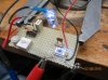
This is my second attempt with making a proper light source for my Omega D5 condenser enlarger based on color LEDs. My first attempt consisted in a large network of green and blue leds (diffusing mode) combined with two highly powerful 15W green and blue leds used as punctual source (placed in the middle of the board). Both green and blue channels were current controlled independently. The head could be used as a diffusing light source with a piece of diffusing plastic window instead of the 3x condenser lenses or as a condenser light source when the light source was replacing the standard light bulb.


Omega D5 new light source V1 by stormpetrel_geek_mode, on Flickr


This light source can be seen working on the video below. Sorry it is in french but the interesting bits are at 1m30 and at 2m35.

[video=vimeo;51559600]http://vimeo.com/51559600[/video]

At this time, I was not enough aware with the principle of a condenser enlarger. There were no problem with the diffusing setup but at the end I realized I would prefer to use my enlarger mainly as a condenser enlarger. Unfortunately I did not take into account the formation of the image of the light sources on the film plan (slight offset between the green picture and the blue picture) , said differently the light source should be perfectly uniform which would require the use of a diffusing dome as the two main LEDs do not act as a perfect unique punctual source despite the short distance separating them). Unfortunately there was not an easy way to integrate such diffuser on my first prototype and also due to the asymmetrical design. The diameter of the diffusing dome is also critical in this application as the condenser creates a magnified image of the source which have to cover the full surface of the film. (small dome => bad film covering). This is not a surprise for the experienced "darkroomers". Ideally the size and the position of the diffusing dome should match the size and the position of the light bulb recommended by the enlarger manufacturer.
The second problem was the wavelength of the LEDs (navy blue and green). As we will see below they are not the most suitable wavelengths, so I have done a bit of research optimizing the new light source.

I would like to share those information with the community as it might be useful for your future own design.


* photographic paper sensitivity

I did an extensive review of the the light sensitivity of all the photographic papers available on the market nowadays. Unfortunately it was not possible to get the datasheets from all the manufacturers but still we have enough information to optimize the wavelength of our leds.
I have split the compilation into 3 groups: normal variable contrast papers, warmtone variable contrast papers and fixed grade paper.
The light sensitivity unit is an arbitrary unit. The interesting information here is at which wavelength each paper is the most sensitive and at which wavelength the control of the grade is done.


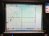
Normal variable contrast papers:


Variable contrast paper sensitivity by stormpetrel_geek_mode, on Flickr

As you can see on the graph, most of the papers are quite sensitive in the violet domain (400-425nm). Note the light sensitivity is a log scale and the sensitivity of many paper drops significantly in the blue. Regarding the control of the grade, this happens between 500nm and 575nm but mainly between 520-525nm (yellow green).


Warmtone VC papers:


Warmtone variable contrast papers sensitivity by stormpetrel_geek_mode, on Flickr

For the warmtone picture, the Ilford paper behaves like the normal VC papers however this is not the case with the other papers. Grade control is performed between 520-530nm for the Foma paper and at above 545 for the Forte paper. In the low side of the spectrum, we see that the Ilford paper is more sensitive in the violet area compared to the 2 others papers which are more blue sensitive (I wonder if there is a mistake in the Forte paper datasheet).


Fixed grade papers:


Fixed grade papers sensitivity by stormpetrel_geek_mode, on Flickr

Fixed grade papers are completely different beasts. There are very sensitive to the green light (475-500nm).


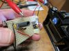
Based on all those information, I have selected the following wavelengths for the LED of my new light source: 420-425nm violet and 520-525nm (yellow green). Those are the wavelengths where I will have the best bangs for my bucks based on my use (variable constrast papers). The new light source consist in 12x 3W 520-525nm green LEDs and 9x 420-425nm violet 3W LEDs spread on a 6cm of diameter PCB. The second board with 4x far red 1W led is stacked onto the first board (the red LEDs are used as an inactinide light source). This boards is mounted on the first board.


Omega D5 enlarger head - leds V2light source by stormpetrel_geek_mode, on Flickr


Omega D5 enlarger head - leds light source V2 by stormpetrel_geek_mode, on Flickr

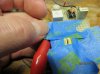
The diffusing dome comes from a Philips energy saving 18W bulb (OD=69mm)


philips-ambiance-soft-e27-18w-100w by stormpetrel_geek_mode, on Flickr

Next post: illumination modelling.
 

stormpetrel

Group owner
#2
Illumination modelling
-------------------------


Ok this model is over killing but it was for me a way to check that the diffusing dome + LEDs light source act as a uniform source. This would have saved me $200 with my first prototype! It is also an exercise for a more ambitious project (a light 8x10 enlarger using a Fresnel lens from an overhead projector).

Optical modelling is quite useful to check a prototype however keep in mind that this model mights differ significantly from the reality.
As I could not find any information regarding the focal length of the lenses used in the condenser of my Omega D5, the focal lengths used in the model are based on the geometrical dimension of the real lenses.


Omega D5 enlarger - optical model by stormpetrel_geek_mode, on Flickr

The light source is this one described previously with 12x yellow green LEDs and 9x violet LEDs. The diffusing dome is based on the Philips energy saving bulb (OD=69mm).
The enlarger lens is made of single a converging lens (not necessary, just for fun).

The illumination modelling is performed with a ray tracing software.

Omega D5 enlarger - Ray tracing by stormpetrel_geek_mode, on Flickr

Here are the results:

* No plano-convex lens in the 135mm tray (150mm lens configuration).


Green light distribution on a 4x5 cut sheet film:

Illumination of a 4x5 cut sheet film with the top plano-convex lens placed in the 150mm tray (green leds only) by stormpetrel_geek_mode, on Flickr

Violet light distribution on a 4x5 cut sheet film:

Illumination of a 4x5 cut sheet film with the top plano-convex lens placed in the 150mm tray (violet led only) by stormpetrel_geek_mode, on Flickr

Both violet and green light distribution on a 4x5 cut sheet film:

Illumination of a 4x5 cut sheet film with the top plano-convex lens placed in the 150mm tray (violet+green leds) by stormpetrel_geek_mode, on Flickr

Those results look promising. The illumination is even on all the surface of the film and we can not see any offset between the green and the violet channels (at least at this resolution).

* Plano-convex lens set in the 135mm tray (135mm lens configuration).

Both colors:

Illumination of a 4x5 cut sheet film with the top plano-convex lens placed in the 135mm tray (violet+green leds) by stormpetrel_geek_mode, on Flickr

We can see the light coverage is not as good as previously however the illumination is stronger at the center which makes this setup a better option for 6x9 film enlarging.
Note the blueish color is different from the previous case due to a different mixing ratio of the green sources with the violets sources.


I have also simulated the illumination of the print just for fun. The focus is not properly done and the single lens suffers from all the optical aberration existing on earth but still, we can have a rough idea about the illumination of the print (here 40cm x 32cm):


print 40cm x 32cm - 150mm tray (violet+green leds) by stormpetrel_geek_mode, on Flickr


It is time to switch on the solder iron and check that this new light source works as expected!
 

stormpetrel

Group owner
#3
The LED driver.
------------------

The easiest way to light a LED is to connect the LED to a voltage power supply with or without a limiting current resistor (depending on the voltage applied). PWM or pump charge circuit might also be used. Unfortunately those are not good solutions to have a constant light emission.
When a fixed voltage is applied to a LED, the current going through the LED drifts due to the temperature increase in the junction. As the number of photons emitted by the LED is proportional to the current crossing the junction, the light emission changes till the thermal equilibrium is not reached. The best way to stabilize the light emission is to drive the LED with a stable current source. This is how laboratory lasers are controlled (a semiconductor laser is very close to a LED)

I propose here a programmable current source using the OPA548T which can drive LEDs up to 3A at 20VDC


LED driver by stormpetrel_geek_mode, on Flickr

This designs works perfectly well as you can see on the video posted at the beginning of this thread.
Ideally with U/I power amps, resistors should be matched (making a perfect U/I converter) but in our case (unipolar design + OPA548 technology) it creates an unstable situation when the driver is switched on. This problem is solved by increasing slightly some resistors value (1.1k instead of 1k and 49.2 instead of 47k) introducing a shift in the function transfer (see simulation below).


LED driver transfer function simulation by stormpetrel_geek_mode, on Flickr

This simulation also shows the effect of the current limiting resistor programmed at 1.02A (the limiting resistor here is 56k instead of 39k as used in the schema above).
It is important to program this resistor value accordingly to the specs of the LED to avoid blowing up your LED!

The driver is fully operational and here is an example of a measured function transfer (the current limit is programmed here at a higher value)

LED driver transfer function measurement by stormpetrel_geek_mode, on Flickr

The driver can be used in different ways. An easy way would be to control the input voltage with a pot (manual control) but in my case I prefer to use a multi-channel 16bits Digital to Analog converter allowing the control of 5 LED drivers simultaneously.
This DAC is controlled by a home brewed PC software/µc board. Thanks to this solution, it was possible to go further in the control of the light emission by doing a linearization of the transfer function curve above. It is then possible to set directly the wanted intensity of light instead of adjusting the tension....
 
#4
Désolé je vais parler en français, mon anglais est trop pauvre.
Mais quel est votre retour sur l'utilisation de cette nouvelle source de lumière pour vos tirage N&B?
Merci
 

stormpetrel

Group owner
#5
Salut Yann

La techno fonctionne très bien mais je suis passé, depuis, a un Durst 139 que j'ai évidemment équipé d'une tête LEDs DIY a 4x canaux (bleu, cyan, vert et rouge).

J'ai 5 drivers qui contrôlent les reseaux de LEDs suivants:
16x LEDs bleues ~440nm 3W (ebay techno EPILEDS ?) (4x branches de 4x led en parallèle, 14V 2.1A)
30x LEDs cyans 485nm 3W ref XPEBBLL10000201 (6x branches de 5x LEDs en parallele, 16.5V 2.1A)
30x LEDs vertes 535nm 3.5W ref XPEGRN-L1-0000-00D01 (6x branches de 5x LEDs en parallele, 16.5V 2.1A)
4x LEDs rouges 660nm 5W LZ1-00R200 (en serie 11.2V 1A) pour le focus.


Le réseau des LEDs cyans est sur une deuxième carte qui se superpose a la carte principale mais qui est perforée pour laisser passer la lumière produites par cette derniere.

On peut voir la tête dans sa première version ici sans la carte Cyan
https://www.flickr.com/photos/stormpetrel_geek_mode/12337513214/
J'utilisais alors des LEDs UV a a la place du bleu mais j'ai prefere repartir sur du bleu pour la dernière version.


Je suis très heureux de cette nouvelle tête pour le tirage N&B.
C’était un peu laborieux de calibrer proprement la tête pour générer les grades de manières correcte (cad tels que définis dans la norme ISO 6846) mais maintenant c'est Nickel!
J'utilise la source a 10% de sa puissance max a f22 quelques soit le tirage (je ne fais cependant pas de grand tirage) ce qui indique que des LEDs moins onéreuses de 1W au lieu de 3W conviendraient parfaitement.

La source ne chauffe absolument pas.
Elle est parfaitement stable et peut être ajustée au pouilleme grâce a l'asservissement en courant.

Grâce au réglage indépendant de chaque canaux, il est possible de compenser de manière automatique les variations d'exposition lors d'un changement de grade.
J'ai réglé la tête de telle manière a ce que la zone VIII (hautes lumières) restent inchangées lors d'un changement de grade a temps d'exposition constant (ce qui n'est pas le cas avec une tête couleurs ou une tête multigrade)

Du coup pour le tirage je procède de la manière suivante.
Je me place en grade 2.5.
* Premier test: j'expose pour trouver le bon temps ou les hautes lumières sont bonnes.
* Second test: je travaille avec ce temps et je fais alors varier le grade entre 00 et 5 par échelon de .25 pour trouver les bonnes ombres (les hautes lumières ne bougent pas grâce a la calibration de la tête!)
Voila !

Je ferai un résumé de la calibration et de la nouvelle tete sur APUG d'ici deux mois.

A+
Dominique
 
#6
Merci pour ta réponse (je te dis tu? c'est plus sympa...),

Je rébondis sur ta réponse :
- Pourquoi avoir abandonné le violet à 420nm pour revenir au bleu royal à 440nm?
- Quel est l'utilité d'avoir intégré du cyan? Le vert et le bleu ne suffisent-ils pas? Le rouge est là pour le confort...


Je suis parti sur la même configuration que votre réalisation pour votre Omega D5 à condensateur.
Je réfléchi à tout ça pour l'intégrer à une tête durst 1200 N&B à condensateur (du 35mm au 4x5) normalement illuminée par une lampe opaline de 150W.
Voilà la configuration que j'ai choisi, le plagia est flagrant :
- 12 x led verte à 525nm
- 8 x led violet à 420 nm, ou bleu à vous de me dire...
- 4 x led rouge à 460 nm
tout ça piloté par 5 drivers, lui même piloté par un arduino en PWM.
je me suis beaucoup inspiré de votre PCB circulaire pour faire tenir les 24 leds dans un cercle de 7cm de diamètre.
Je compte aussi utiliser un globe d'ampoule pour homogènéiser tout ça.
Sur le PCB j'ai effectué des via thermique pour amener la chaleur sur l'arrière de celui-ci. Et enfin un gros dissipateur de 10 x 10 x 10 cm refroidira tout ça.

J'aimerais vraiment avoir ton retour et tes conseils sur ton travail avec l'omega D5 équipé en leds car c'est peu de chose prêt la même configuration que sur le Durst 1200 avec tête B&W à condensateur :
- Dois-je augmenter la taille du dissipateur?
- est ce qu'il y a trop de led? 12 x verts + 8 x bleu.
- est ce que la source led sera trop lumineuse donc comme toi j'utiliserai les leds à seulement quelques % de sa capacité et donc elles ne chaufferons pas
- dois-je poncer les globe des led pour aider à diffuser?
- l'homogéniété de la source (leds + globe d'ampoule) est-elle suffisante, même en configuration argandisseur à condensateur? J'ai lu quelques fois que pour la agrandisseur à lumière diffuse ça marchait très bien, mais qu'en lumière ponctuelle ou semi ponctuelle il pouvait y avoir des problèmes.

Pour tout ce qui est calibrage pour avoir une exposition des hautes (ou basses d'ailleurs) lumières constante avec tous les grades, je n'ai aucun soucis la dessus, je me suis déjà beaucoup amusé avec une tête couleur et une stouffer pour la calibrer de la même façon. Le principe est le même.

Je précise que je tire du 6x6 et du 4x5 plus rarement.

Merci et bonne nuit de l'autre côté.

Yann
 

stormpetrel

Group owner
#7
Salut Yann

Au sujet du choix des LEDs bleues, j’étais parti avec des LEDs UV sur mes premiers protos parce que les papiers multigrades sont plus sensibles dans l'UV que dans le bleu, cf graph de sensibilité dans les messages précédents. Je m'orientai aussi à l’époque, vers une tête universelle qui puisse servir aussi pour les procédés alternatifs gourmand en lumière UV. Bien que le proto fonctionnait très bien électriquement parlant, j'étais ennuyé par le fait que les objectifs d'agrandisseur coupe a 400 ~nm sauf les Nikkor qui transmettent jusqu'a 380nm-390nm. Ce n'est pas la peine de produire des photons a 390nm si c'est pour derrière se les faire absorber par l'objectif et avoir des résultats erratiques en terme de tirage N&B.... Avec les premiers essais du proto n°1, j'ai pu aussi constater que la puissance lumineuse balancée par la source était telle que ce n’était pas la peine d'aller exploiter la sensibilité max du papier dans l'UV.... Un autre problème au quel je n'avais pas pensé, est la fluorescence du papier (pense au chaussettes blanches dans une boite de nuit éclairées avec les lampes noires). Je me demandais dans quelles mesures cette fluorescence pouvait réémettre dans l’émulsion des photons s’étendant jusque dans le vert et pourrir le tirage sur papier multigrade... Je ne voulais pas prendre ce risque donc je me suis éloigné de cet écueil d'abord avec des LEDs de 425nm puis avec des LEDs de 440nm pour réduire encore plus cette fluorescence.

Pourquoi la couleur Cyan? Et bien parce que quand tu commences a te plonger dans les docs techniques sur les papiers multigrades, tu apprends que certains fabricants de papier (dont Ilford) couchent sur leurs papiers trois émulsions différentes pour gérer le contraste: une émulsion sensible dans le vert, une dans le cyan et la dernière dans le bleu. En fait ce n'est pas tout a fait vrai, il faudrait dire, que l’émulsion verte est sensible au bleu,cyan et vert, que l’émulsion cyan est sensible au bleu et au cyan et que l’émulsion bleue n'est sensible qu'au bleu.

La couleur cyan permet de résoudre un problème de perte de tonalité dans les grades les plus doux. Je te recommande la lecture de ce document qui décrit très bien le rôle du cyan dans les papier multigrades: www.darkroomautomation.com/support/appnotevcworkings.pdf (page 5) on retrouve aussi l'explication dans les docs d'Ilford.

Or quand tu superposes des LEDs vertes avec des LEDs bleus, tes yeux perçoivent une couleur Cyan mais en réalité, il y a un trou dans cette bande spectrale (cf graphe du spectre d’émission des LEDs dans les messages précédents), trou que ne connaissent pas les sources a filament tungstène puisqu'elles émettent un spectre continue jusque dans l'IR . Il n'y a quasiment pas de photons émis dans le Cyan. Cependant je n'ai pas pu trouver d'infos techniques détaillant les caractéristiques spectrales de cette émulsion cyan. J'ai donc ajuster la longueur d'onde cyan pour être pile poile a mi-chemin entre le vert et le bleu histoire de combler le fameux trou. C'est pour cela que j'ai ajoute des LEDs cyan a 485nm (=(440nm+535nm)/2).

Pour le moment je n'ai calibré la tête qu'avec le vert et le bleu mais je compte bien intégrer le cyan pour les "soft grades" des que j'aurai du temps de libre. J'utilise cependant la lumière Cyan pour faire la mise au point de netteté. Je me suis aperçu que j’étais légèrement hors focus lorsque je faisais la mise au point avec les LEDs rouges... Ces dernières ne me servent plus qu'a cadrer l'épreuve.


Pour le PCB, je ne sais pas si tu as deja routé ta carte mais je te conseille de prendre des LEDs de compétition avec de très fort rendement.
Un très fort rendement implique moins d'effet joule a puissance lumineuse constante. Comme tu vas faire tenir pas mal de LEDs sur une petite surface, mieux vaut optimiser l'aspect thermique. Pour les vertes, je te conseille vivement les XPEGRN-L1-0000-00D01 dispo chez www.mouser.com. C'est de la bombasse!


Pour les cyans, c'est a toi de voir, peut être pour une première version je ne m'emmerderai pas avec les cyans surtout si tu n'as pas la place sur le PCB a moins que ta photographie te fasse tirer a grade 00 ou 1.

Pour LEDs bleues, c'est du chinois sur ebay. Cherche 3W + 440nm et tu vas les trouver.
Exemple http://www.ebay.com/itm/10Pcs-3w-Po...911?pt=LH_DefaultDomain_0&hash=item19daa5cef7. Verifie bien avec le vendeur que c'est bien du 440nm


- est ce qu'il y a trop de led? 12 x verts + 8 x bleu.
En quantité, je mettrai plus de bleu que de vert. Les LEDs vertes on un tel rendement que ce n'est pas la peine d'en mettre plus que les bleus. De plus en pratique,
on utilise deux fois moins de lumière verte (n'oublie pas que l’émulsion bleue ET l’émulsion verte réagisse a la lumière verte). Je partirai donc sur 12x bleues et 8-9x vertes. Tu peux mettre les LEDs rouge sur une carte mezzanine

- est ce que la source led sera trop lumineuse donc comme toi j'utiliserai les LEDs à seulement quelques % de sa capacité et donc elles ne chaufferons pas
Plus une LED chauffe plus elle dévie en couleur donc mieux ne vaut pas utiliser une LED au delà de 80% de son max (limite purement arbitraire). D'un autre cote, il est difficile de régler les LEDs a quelques % car on fonctionne dans la partie non linéaire de la LED....

- dois-je poncer les globe des led pour aider à diffuser?
Une LED CMS, c'est hyper fragile, j’éviterai cette opération.


- l'homogéniété de la source (leds + globe d'ampoule) est-elle suffisante, même en configuration argandisseur à condensateur? J'ai lu quelques fois que pour la agrandisseur à lumière diffuse ça marchait très bien, mais qu'en lumière ponctuelle ou semi ponctuelle il pouvait y avoir des problèmes.

Question design, ta source doit avoir au-moins le même diamètre que ton ampoule d'origine sinon ça va vignetter.
Mon Durst 138 est un agrandisseur a condensateur (https://www.flickr.com/photos/stormpetrel_geek_mode/12337513214/).
Si tu regardes bien sur la photo, on peut voir sur la droite la source original. Il s'agit d'un verre dépoli plan derrière lequel ce cache une ampoule krypton de taille plus réduite. Le rôle du condenseur est d'agrandir l'image de cette source sur la surface d'impression. En pratique le constructeur décale un chouya la source pour justement ne pas former l'image du filament! Tu n'as pas besoin d'avoir une source LED spherique. Tu peux tout simplement accrocher un disque de plastique blanc translucide devant tes LEDs, suffisamment loin des LEDs pour que la lumière soit homogène sur ton diffuseur. La taille du disque doit correspondre a la taille de ton ampoule (regarde dans la doc de ton agrandisseur les caractéristiques de l'ampoule d'origine). La position du disque est critique et doit se trouver a l’emplacement de l'ampoule. Mon agrandisseur a un miroir réfléchissant ainsi qu'un tiroir pour placer des filtres IR. C'est aussi un bon emplacement pour mettre le diffuseur si tu ne peux pas le fixer sur ta source.

De plus si ta source est trop puissante cad que tu travailles en régime non linéaire alors tu peux augmenter l’épaisseur de ton diffuseur pour bouffer 2-4 stops.


Sur mon agrandisseur la lumière est super homogène même en configuration 5X7.

- Dois-je augmenter la taille du dissipateur?
C'est deja un beau morceau d'alu. Plus c'est gros mieux c'est mais le mien ne fait que 3cm d’épaisseur (afin de pouvoir entrer dans cavité de la tête) Fais très attention au couplage carte/dissipateur, c'est presque plus important que la taille du radiateur.
utilise de la graisse thermique de compétition NON conductrice (genre celle qui est utilise pour les CPU de PC).
J'ai mis sous ma plaque une feuillard conducteur de chaleur mais non conducteur électriquement pour éviter des courts-circuits carte/dissipateur
Laisse le maximum de cuivre sur tes cartes. Utilise une double face. Si tu regardes bien sur les photos des PCB publiées sur ce fil, tu peux voir que j'ai mis une tetrachié de via sous les LEDs. Pour le montage des LEDs, il te faudra faire ca au four et a la pate a souder, hors de question de le faire au fer a souder.
Lis bien les datasheets de tes LEDs et en particulier les recommandation de footprints.

Comme ta source est dans un espace confine, n’hésite pas ajouter un ventilateur pour brasser l'air surtout si tu as tes rouges sur une carte mezzanine (et donc non connecter au dissipateur). J'ai mis deux ventilateurs dans la tête d'agrandisseur. Tu peux coupler leur allumage a l'activation des LEDs grace a ton arduino.

Une remarque au sujet des PWM. Pour moi c'est loin d’être la panacée. Ok tu vas pouvoir contrôler tes LEDs avec, mais ça va être une commande en tension et ça c'est le plus merdique qui soit pour une LED Le nombre de photons émis par la diode est directement proportionnel au courant qui passe dans la jonction et non pas la tension aux bornes de la jonction. Concrètement, ça va être difficile de contrôler la puissance d'émission des LEDs a faible niveaux (domaine non linéaire) ou quand elles vont commencer a chauffer (a tension identique les LEDs vont émettre moins de photons). Mieux vaut coller a ton arduino un DAC et des convertisseur tension/courant de puissance.


A+
Dominique
 
#8
Stormpetrel,
The french i took in high school is a very rusty, can you possibly repost in english? Im fascinated by this project and hope to make an LED cold head for my Omega D2 soon. I have many questions, so I'd like to stay with this thread.
 

stormpetrel

Group owner
#9
Hi Bergytone

I will soon. The omega enlarger has been replaced by a Durst 139 since (same as Durst 138 but under steroïd). Anyway the hardware remains the same except there are more LEDs on the board and I have also added the cyan color to the blue, green and red existing channels.

After an intensive calibration phase, my last version of LED head works like a charm and is properly calibrated for each VC papers I use against ISO6846 (which defines the paper grades) with the tiny difference I placed the "speed point" is in the highlights instead of the midtones.

Thanks to this calibration I can now change the grade without changing the highlight values of the print (at same exposure time) which is not the case with standard multigrade head or colour head as their "speed points" are placed in the midtones. This is a real advantage of an adjustable LEDs head compared to a conventional head.

Practically it means that I do my first strip chart at grade 2-3 to find the right exposure time for the highlights (zone VIII). Once found, I do a second strip chart with the same exposure time but with changing the grade of 0.5 step from 00 to 5 (which is a breeze with my LED head) The highlights of the strip chart remains the same as the head is calibrated for this purpose, but the shadows change with the grade. I keep of course the grade with the best shadows. Et voila!

I will details the whole calibration procedure and also give the calibration value I got for some multigrade papers I use. People using the same blue & green wavelength LEDs could use those value to set the grade of their head without spending time in an intensive calibration....
 
#10
Hello,

Sorry but my english is very bad, but Stormpetrel can explain it in english as well as possible.

J'y vois maintenant un peu plus clair.

La solution du DAC et du convertisseur Tension / courant ne me semble pas très simple.
Pour le DAC un carte comme ça et ça roule : https://www.sparkfun.com/products/12918
Mais pour le dirver, je dois m'inspirer de ton schéma (ci-dessus plus haut)
Si j'ai bien compris, en sortie des drivers la tension reste fixe et c'est le courant qui varie en fonction de U_LED (sortie du DAC).

Voilà ma configuration :

BLEU : 2 branches de 6 en série soit 21,6V avec 1,4A Max
440 nm
3,4 - 3,8 V
700 mA


VERT : 2 branches de 4 en série soit 13,2V avec 1,4A Max
525 nm
3,2 - 3,4 V
700 mA


ROUGE : 1 branches de 4 en série soit 10V avec 0,7A Max
660 nm
2,2 - 2,8 V
700 mA

J'en déduit que je peux utiliser seulement 3 drivers, un pour chaque couleur et qu'il faut que j'adapte chaque driver à chaque canaux de couleur.
R6 limite le courant de sortie.
Comment j'adapte la tension de sortie sur ton schéma pour le dimensioner à mes différentes branches de leds?

OU ALORS : peut être que ce genre de module (Ebay : DC-DC-Step-up-Power-LTC1871-Supply-3-5V-35V-100W-Converter-Module-LED-Display), collé au cul du DAC ferait l'affaire ?
Au prix de la bête et au temps gagné j'y vois un intérêt, sutrout que je n'aurai pas de PCB à faire fabriquer ou à bricoler. Mais je ne suis pas sur que ce soit la même chose.

Je m'aperçois que je dis des conneries car il me faut une entrée pour piloter le bébé, ce qu'il n'y a pas sur ce module... :blink:

Tu vois bien que mes connaissances en électronique sont empiriques !!!! :whistling:

Est ce qu'il n'existe pas déjà un module tout fait de step up avec contrôle en tension ou en pwm? J'ai pas l'impression...

Dans l'attente de te lire.

A très bientôt
Yann
 

stormpetrel

Group owner
#11
>La solution du DAC et du convertisseur Tension / courant ne me semble pas très simple.
>Pour le DAC un carte comme ça et ça roule : https://www.sparkfun.com/products/12918

Ca doit le faire.


>Mais pour le dirver, je dois m'inspirer de ton schéma (ci-dessus plus haut)

Si tu veux le top en terme de contrôleur de LED, affirmatif.


>Si j'ai bien compris, en sortie des drivers la tension reste fixe et c'est le courant qui varie en fonction de U_LED (sortie du DAC).

Non pas vraiment, c'est le courant qui reste fixe. Le driver de LED que je propose est un convertisseur tension/courant. Autrement dit le courant débité par le driver est directement proportionnel a la tension appliquée a l’entrée du driver (cad la tension de ton DAC dans notre cas).
Le gain de conversion est fixé par les résistances autour de l'ampli-op de puissance.
Même si la tension de ton DAC ne bouge pas d'un pouilleme, la tension aux bornes de ton réseau de LEDs peut varier sensiblement, par contre le courant générer par le driver et qui circule dans tes LEDs restera parfaitement stable et du coup la puissance lumineuse aussi.


>J'en déduit que je peux utiliser seulement 3 drivers, un pour chaque couleur et qu'il faut que j'adapte chaque driver à chaque canaux de couleur.

Yes sir!

>R6 limite le courant de sortie.

Yes sir

>Comment j'adapte la tension de sortie sur ton schéma pour le dimensioner à mes différentes branches de leds?

Pas besoin. Du moment que tu mettes 22VDC sur la pinoche 5 de l'OPA548T, ton driver se chargera de trouver la bonne tension pour l’intensité que tu auras programme avec ton DAC.

Supposons que tu bosses avec du 3.3V et prenons le cas du canal bleu.
Avec ta carte MCP4725, ta tension de sortie max de ton DAC sera de 3.3V si tu l'alimentes en 3.3V.
Comme Imax est 1.4A on va déjà fixer R6 a 37k pour programmer le courant max de l'AO de puissance. Ca va protéger tes LEDs d'une éventuelle vaporisation en cas de fausse manip avec le DAC (cf datasheet de l'OPA548T, equation n°1)
Tu veux 1.4A quand ton DAC est au max, soit a la valeur de 4096 (le max pour un 12 bits).
Sachant que le gain du driver courant tension est de 0.54A/V, cela implique qu'il faut 2.6V a l’entrée du driver (2.6x0.54=1.4A)
Or a 4096, ton DAC va produire une tension de 3.3V qui est supérieure a 2.6V on peut faire avec mais on va perdre un peu de dynamique car toutes les valeurs au-delà de 2.6V ne serviront a rien puisque on aura atteint les 1.4A et que ton driver ne pas émettre plus a cause de R6.
On va profiter qu'il faut absolument un deuxième Ampli-op entre ton DAC et l'OPA548 (la sortie du DAC n'est pas suffisamment costaud pour attaquer le directement l'OPA548T) pour adapter le signal de ton DAC. Dans mon cas c'est un simple LM324 monte en ampli non inverseur avec un gain de 2 (j'avais besoin de cela pour produire des courants > 2A). Dans ton cas tu peux le configurer en suiveur (R3 non connecte, R4 court-circuit). Tu peux même connecter a ton DAC un pont diviseur constitue d'une résistance de 15K et une de 3.3K. Apres ton pont diviseur ta tension max de 3.3V deviendra 2.7V (3.3*(15000/(15000+3300))= 2.7V) et c'est cette tension qu'on injectera dans ton montage suiveur et que l'on retrouvera a l'entree de l'OPA548T
Certes on dépasse un peu les 2.6V mais c'est bien comme ça. Le max sera obtenu pour une valeur de ~3950

Au-lieu du pont diviseur, une autre approche consisterait a changer le gain du convertisseur courant/tension...


>OU ALORS : peut être que ce genre de module (Ebay : DC-DC-Step-up-Power-LTC1871-Supply-3-5V-35V-100W-Converter-Module-LED-Display), collé au cul du DAC ferait l'affaire ?
>Au prix de la bête et au temps gagné j'y vois un intérêt, sutrout que je n'aurai pas de PCB à faire fabriquer ou à bricoler. Mais je ne suis pas sur que ce soit la même chose.
je ne le sens pas trop. N'oublie pas que le plus puissant de tes canaux, le bleu, fait 30W max... donc pas besoin d'un bouzin a 100W.
Un truc du genre http://www.ebay.com/itm/7-12-x-3W-3...548?pt=LH_DefaultDomain_0&hash=item3cf0d41c94 ferait peut-être mieux l'affaire?
Mais c'est a tester.

A+
 
#12
Hi Stormpetrel,
I am closely following your postings by using Google translate, and even though it's not a very good translation I can understand what you and barbaryann are discussing. I will be experimenting with an LED light source for my Omega D2, as the notion of a variable contrast head sounds great. I have two cold heads, an Aristo and a Zone VI, both have the blue/white bulb instead of the V54 bulb, so they don't work well with multigrade paper. I will be selling them soon. Having full variable contrast control with a cold head is much more desirable.

Did you ever try using your light source as a diffusion source instead of as a condenser design? I would think it would eliminate all of your issues with the size of the source matching the enlarging bulb. Is the problem with even light distribution more difficult with a diffusion head?

There are many 'dimmable' LED current source drivers available, which have a very wide range of driving current and are controlled by a DC input signal. It would simplify the design, but might be a little more expensive. One device is sold under the name "buckpuck" by LEDdynamics, and can be seen on digikey.com . I would like to use three of these to drive the LEDS.

It sounds like the 3W LEDs are more powerful than you need for this application. Would 1 watt LEDs work, if used in the quantities you suggest? I don't do huge enlargements, so I need minimal light. It sounds like from your tests you were running the 3w leds at 10% power or less.

Here's what I learned from your posts:
use 12 of the Chinese 440nm LEDs, maybe 3 banks of 4
use 9 of the Cree royal blue LEDs (from mouser) 535nm in three banks of three.
add some red leds for focusing.
Are the cyan LEDs necessary? I understand that you want to use them to fine tune the contrast. Can acceptable results be obtained with just the blue and green?
I look forward to your future posts, even in French! The data about the ratios of the two light sources vs. contrast and how to calibrate it all will be invaluable....
 

stormpetrel

Group owner
#13
Hi bergytone

I m quite busy at the moment but i will make you a big fat reply next week with some recommandation for your diy head.
Dom
 

stormpetrel

Group owner
#14
Hi Bergytone

You will find some replies to your question in the LED light source for Durst 138/139 thread


My last posts with Barbaryan were written in a slang French so google translate mights have been a bit lost in the translation.

To sum up my previous french posts :
* I have replaced my omega enlarger with a durst 139 (durst 138 under steroid).

* I have replaced the exotic krypton (or xenon?) light bulb of the durst 138 with a home brewed LEDs head.

* Here are the LEDs used on the Durst 139/138 headlight.

30x LEDs cyan 485nm 3W ref XPEBBLL10000201 (array of 6x5, 16.5V 2.1A)
30x LEDs green 535nm 3.5W ref XPEGRN-L1-0000-00D01 (array of 6x5, 16.5V 2.1A)
4x LEDs red 660nm 5W LZ1-00R200 (Array of 1x4 11.2V 1A) used as safe light.
The LEDs listed above are manufactured by reliable company and their datasheet are perfectly well documented. I bought them from Mouser & Digikey

Unfortunately I could not find powerful blue LEDs at Mouser or Digikey so I bought them from Chinese ebay retailers without any datasheet. I suspect from the shape of the die they are EPILED technology.


>Did you ever try using your light source as a diffusion source instead of as a condenser design? I would think it would eliminate all of your issues with the size of the source matching the enlarging bulb. Is the problem with even light distribution more difficult with a diffusion head?

This is not as complicate as it looks to replace a condenser light source with an array of LEDs board. In a condenser enlarger, the big condenser lenses magnify the light source image and project it on the easel. In fact, enlarger manufacturer moves the light source slightly away from the object plane to avoid the formation of a sharp picture of the light source on the easel. I was not aware of that and in my first attempt to retrofit the omega, I could see the image of the LED junctions on the print! this problem could be easily solved by using a diffuser (a simple piece of white plastic).

With a condenser enlarger, you have to respect the size of the original light bulb.

It is what I have done here with my Durst 138.

https://flic.kr/p/jNdYR5 by stormpetrel_geek_mode, on Flickr

The original light source is on the right and the new one is on the left. They have both the same diameter!
I could have added a circular diffuser (white plastic or ground glass) above the LED board, but there is no point for that in the case of the Durst 138 as there is tray for a heat filter/ diffuser between the the light source and the mirror. This is where I put the diffuser.
The light is perfectly even from 35mm up to 5x7!

>There are many 'dimmable' LED current source drivers available, which have a very wide range of driving current and are controlled by a DC input signal. It would simplify the design, but might be a little more expensive. One device is sold under the name "buckpuck" by LEDdynamics, and can be seen on digikey.com . I would like to use three of these to drive the LEDS.

Many options exist to drive LEDs as PWM or CCR. In this case, I prefer Constant Current Reduction despite the low efficiency of this technique compared to PWM. As the number of photons produced by the LED is directly proportional to the current going through the junction, if you control the current, you control the light! A tension/current converter does that perfectly well with a great accuracy. It also possible to control the LED at very low level few % which is not the case with most PWM. It is also easier to calibrate as you can easily measure DC current with an ampere meter.
Here are interesting document detailing pro & con of both design (google 2F367-2035_LED_white_paper.pdf 048360a_PWM_vs_CCR_LED_App_Note.pdf )

>It sounds like the 3W LEDs are more powerful than you need for this application. Would 1 watt LEDs work, if used in the quantities you suggest? I don't do huge enlargements, so I need minimal light. It sounds like from your tests you were running the 3w leds at 10% power or less.

For medium enlargement, there is no point to have a such powerful head indeed. 1/4 of the max power would have been enough (~25W per channel). In your case 10-15W per channel should be enough. However try to use as much LEDs as you can as it is a good way to spread the heat on the board. In my case, my extensive calibration showed that I could easily do with 45W instead of 90W for the green channel). This mights be due to the difference of efficiency between CREE LEDs and EPILEDs blue....
 
#15
hey stormpetrel,
Thanks for the update. Based on what you've learned, I think I could use an array of 3 x5 for the blue, and 2 x5 for the green since you've inferred that you really only need half the quantity of the green LEDs vs the blue LEDs to get satisfactory results. It also sounds like you aren't using the cyan LEds yet, that they are for future fine tuning of the contrast. Not sure exactly how many of those i'd need... if I need them at all.

Would it be safe to throw in a few red Leds to 'whiten' the light for focusing?

The "buckpuck"s I was mentioning seem to be constant current device, not using a PWM switched current. It looks like there's a full range of DC output current control based on an analog input control voltage. They seem ideal to use with either a manual (potentiometer) control or a D/A derived DC voltage from a microcontroller.

I haven't had time to get started on this LED head as I'm working very diligently on a pretty high end shutter speed tester with shutter curtain speed measurements. Details are in another thread in this group.

Please give me your thoughts on the LED needs for my lower power light source for my old D2 enlarger. I'm considering bringing a product to market if all goes well.
 
#16
Salut Stormpetrel,

J'ai aussi un Durst 139 avec une lampe xenon et des condenseur et j'ai déjà un morceau de code arduino pour faire fonctionner une grosse led Cree blanche via un driver Meanwell. Mais pour le multigrade, j'utilise le touret Durst...
J'ai l'idée de continuer de développer mon système avec plus de led et pour plus de souplesse mais comme tu sembles avoir bien avancé dans la direction que j'avais choisie, je voulais savoir si tu étais d'accord de partager ton code et ton design de PCB...

Peut-être est-déjà dispo quelque part sur le web? Sinon en privé, pour m'éviter de réinventer la roue?

Meilleures salutations

Bricophil
 

stormpetrel

Group owner
#17
Je viens de m'apercevoir que j'ai dit une connerie dans une des réponses ci-dessus


"- est ce qu'il y a trop de led? 12 x verts + 8 x bleu.
En quantité, je mettrai plus de bleu que de vert. Les LEDs vertes on un tel rendement que ce n'est pas la peine d'en mettre plus que les bleus. De plus en pratique,
on utilise deux fois moins de lumière verte (n'oublie pas que l’émulsion bleue ET l’émulsion verte réagisse a la lumière verte). Je partirai donc sur 12x bleues et 8-9x vertes. Tu peux mettre les LEDs rouge sur une carte mezzanine"


Évidemment l’émulsion "bleue" ne voit que la lumière bleue, l’émulsion "verte" réagit a la lumière verte ET bleue comme indiqué dans un de mes commentaires précédents en anglais.
Par contre je confirme qu'avec les modèles de LEDs que j'ai utilise il aurait été plus judicieux d'avoir un ratio en puissance de 2/3 de LED bleues pour 1/3 de LEDs vertes
 
#18
Très intéressant, bravo pour la réalisation et pour la communication d'information. Je poursuis en anglais pour les participants qui ont des faiblesses en Français.
I see in the Ilford document:
https://www.ilfordphoto.com/wp/wp-content/uploads/2017/03/Contrast-control-for-Ilford-Multigrade.pdf
that there are three emulsions in MG paper. Question: is the "intermediate" emulsion
(A) one with an intermediate sensitivity to normal green (say, 550nm, or whatever)
(B) one with a peak sensitivity at an intermediate wavelength between blue and green (say, 480 or 500nm, or whatever)​
Agreed, the Ilford doc sounds more like (A), but, with broad sensitivity peaks and broad filter responses, the language of the doc might as well describe approximately (B). One hint that (B) might be the case is the three humps (425, 485, 525nm, approx.) in the spectral sensitivity of the multigrade papers that you show in your plot for VC warmrone papers, for Ilford and maybe also Foma; Forte Bromofort being clearly different. The pot for "normal" MG papers is too crowded to comment.

If (B) is the actual case, an Ilford (Foma??) paper might respond differently to 2 colors of LEDs with semi-narrow spectral emission than it does to the MG filters.
 
#19
I see that the topic of cyan LEDs has already been brought up... A report on the 4-color head would be nice, as advertised:
Je ferai un résumé de la calibration et de la nouvelle tete sur APUG d'ici deux mois.
Kind reminder:whistling:
 
Photrio.com contains affiliate links to products. We may receive a commission for purchases made through these links.
To read our full affiliate disclosure statement please click Here.

PHOTRIO PARTNERS EQUALLY FUNDING OUR COMMUNITY:


Ilford ADOX Freestyle Photographic Stearman Press Weldon Color Lab Blue Moon Camera & Machine
Top Bottom