Build a shutter tester for Focal Plane shutters - Cheap, Easy & it Works

Table Rock and the Chimneys

A
Table Rock and the Chimneys

  • 3
  • 0
  • 92
Jizo

D
Jizo

  • 3
  • 1
  • 79
Top Floor Fun

A
Top Floor Fun

  • 0
  • 0
  • 68
Sparrow

A
Sparrow

  • 3
  • 0
  • 83
Another Saturday.

A
Another Saturday.

  • 3
  • 0
  • 141

Recent Classifieds

Forum statistics

Threads
197,407
Messages
2,758,490
Members
99,489
Latest member
WYann
Recent bookmarks
1

pemcg

Member
Joined
Mar 10, 2023
Messages
4
Location
United Kingdom
Format
35mm
PM me for the code

According to the forum rules: "Due to recent spam issues, private messages and classified ad postings to fellow members will not be available until you have posted at least 20 (genuine, not filler) messages in our public forum area." I guess I could post this another 19 times and then PM you :smile:
 

Flighter

Member
Joined
Mar 7, 2023
Messages
261
Location
Scotland
Format
35mm
Hi,
That's great :surprised:)
getting the computer talking to the Arduino is probably the hardest bit.
Should have said, in the Arduino, IDE, in the 'Tools' tab, one has to select the correct board 'Nano'
and just below this, Processor, is one selects 'ATmega 328P (Old bootloader)

I have a dedicated Nano with a program loaded, to update the bootloader on any Arduino, kindly written by Nick Gammon. l load the 'Optiboot' bootloader, which frees some extra program memory.

I couldn't find any 'old bootloader, option initially because my IDE wasn't displaying the 'Processor' option under 'Tools' initially, it took me a while to realise that I had the board set as 'Uno' but once I realised this and changed it to 'Nano' the 'Processor' option appeared under 'Tools' and I was good to go.

I didn't need to do anything for the CH340 driver but from what I read on the internet when trying to solve the missing old bootloader issue that may be because I'm running Linux (Mint 20.3) which already has the driver.

And in other news, my Dupont wires arrived today, just need something to connect them to now!

I'm guessing I should be good for PMs by Monday (5 days) by which time, hopefully, all the parts will have arrived.
 

Flighter

Member
Joined
Mar 7, 2023
Messages
261
Location
Scotland
Format
35mm
You should already be capable of sending PM's! Please let me know if this is not the case.

I don't think I can, but it may be because I don't know how!

I'm a member of another forum that also uses XenForo and when I click on either a member's name or the mail symbol at the top right in that forum I get a 'start conversation' option which I'm not seeing here.

I was working on the assumption that I had to have 20 non-filler posts and be registered for 5 days?
 

koraks

Moderator
Moderator
Joined
Nov 29, 2018
Messages
20,567
Location
Europe
Format
Multi Format
I was working on the assumption that I had to have 20 non-filler posts and be registered for 5 days?

I think it's just the 20 posts, really. You should get this dialog whenever you click someone's username:
1678458727054.png


Anyway, I'll add you to an open conversation about obtaining the code; that should work around the issue for now.
 

Flighter

Member
Joined
Mar 7, 2023
Messages
261
Location
Scotland
Format
35mm
Thanks koraks, much appreciated.

I don't get the 'start conversation' option when I click a username
5E3DF234-E263-4402-95C1-5D4EB6CAA023.jpeg
 
OP
OP

Niglyn

Member
Joined
Feb 26, 2022
Messages
402
Location
Surrey, UK
Format
Analog
Hi Guys,
Sorry for the poor quality photos, I'm working with very little IT.
A couple of photos showing what you can expect to see on the computer screen & the LCD.
The LCD is optional, you can save money by just having the output displayed on the computer screen.


20230310_150536 (002).jpg


20230310_174648 (002).jpg
 
OP
OP

Niglyn

Member
Joined
Feb 26, 2022
Messages
402
Location
Surrey, UK
Format
Analog
Hi Guys,
A photo of the Arduino Nano connected to the LCD. Will show you where the wires go.
A piccy of the two lasers. You can see I have soldered directly to them, rather than using Dupont wires. Red is +5V and black 0V
The sensors have three wires, again red is +5v and black 0V. Each has an additional wire, white going to the middle pin of one sensor, blue to the other. These are the trigger wires, going to pins 2 & 3 on the Arduino.
Really sorry for the poor details, but have very little IT.
Please feel free to ask any questions if you need help.
If you have better pictures of your completed device, please post the photos.


20230310_125652 (002).jpg
20230310_125620 (002).jpg

20230310_125441 (002).jpg
 
  • Niglyn
  • Deleted
  • Reason: updated file posted

Flighter

Member
Joined
Mar 7, 2023
Messages
261
Location
Scotland
Format
35mm
Many thanks Niglyn.

A quick question if I may, what's the reason for soldering direct to the lasers rather than using the Dupont cables?

Or rather 2 questions. All my cameras have a horizontal shutter - I assume that I should placed the lasers and receivers so that they are spaced slightly less then 36mm apart?
 
OP
OP

Niglyn

Member
Joined
Feb 26, 2022
Messages
402
Location
Surrey, UK
Format
Analog
Many thanks Niglyn.

A quick question if I may, what's the reason for soldering direct to the lasers rather than using the Dupont cables?

Or rather 2 questions. All my cameras have a horizontal shutter - I assume that I should placed the lasers and receivers so that they are spaced slightly less then 36mm apart?

Hi,
I space the sensors 20mm apart. They are mounted at a height that a 35mm camera can be held horizontally or vertically between them (I use a spacer under the camera when mounting horizontal). You could mount the rx into a plastic project box and drill small holes for the rx to see through and then place this on the back of the camera. This is the way professional units work. They then only have one diffused light source, rather than mine having two lasers.
You could make a wooden holder similar to mine, but make it much higher and lay it on it's side. the camera could then sit flat on the workbench, with the tester to the side of it.

You do not want to space the sensors right at the edge of the frame. Everything in life take a bit of time to get going, so the shutter curtain may not be quite up to speed at the start. Service manuals often specify a curtain travel speed and also how far apart the measurements should be taken. Canon T70 for examples specifies 20mm.

The reason for soldering the wires, it was easier for me to do it that way and there are less wires to run back to the Arduino. Using Dupont wires maybe much easier for those less familiar with electronics.

Thanks for your interest in this project.
N.
 
OP
OP

Niglyn

Member
Joined
Feb 26, 2022
Messages
402
Location
Surrey, UK
Format
Analog
According to the forum rules: "Due to recent spam issues, private messages and classified ad postings to fellow members will not be available until you have posted at least 20 (genuine, not filler) messages in our public forum area." I guess I could post this another 19 times and then PM you :smile:

Hi, sorry, was difficult to get code to peeps any other way, as I was working just from a phone and had a copy of the code on an email.

Have now posted a copy of the code directly to a post in this thread, hopefully you can get it there, id not, or any problems, please shout.
 

Mamiya_Repair

Advertiser
Joined
Feb 7, 2019
Messages
219
Location
Nevada
Format
Medium Format
Hi,
I space the sensors 20mm apart. They are mounted at a height that a 35mm camera can be held horizontally or vertically between them (I use a spacer under the camera when mounting horizontal). You could mount the rx into a plastic project box and drill small holes for the rx to see through and then place this on the back of the camera. This is the way professional units work. They then only have one diffused light source, rather than mine having two lasers.
You could make a wooden holder similar to mine, but make it much higher and lay it on it's side. the camera could then sit flat on the workbench, with the tester to the side of it.

You do not want to space the sensors right at the edge of the frame. Everything in life take a bit of time to get going, so the shutter curtain may not be quite up to speed at the start. Service manuals often specify a curtain travel speed and also how far apart the measurements should be taken. Canon T70 for examples specifies 20mm.

The reason for soldering the wires, it was easier for me to do it that way and there are less wires to run back to the Arduino. Using Dupont wires maybe much easier for those less familiar with electronics.

Thanks for your interest in this project.
N.

Typical spacing of sensors on commercial shutter speed testers is 32mm for horizontal running shutters and 20mm for vertical running shutters. These sensors are placed diagonally in a block that installs in the film plane so that in this way you can read vertical or horizontal shutter travel times correctly.
 

Flighter

Member
Joined
Mar 7, 2023
Messages
261
Location
Scotland
Format
35mm
Thanks Niglyn, all understood.

I've plenty of offcuts of timber so plan to knock up a wooden holder similar to yours at the weekend. It's probably too much to hope that the lasers and lcd will be in the post tomorrow but hopefully they will come next week.
 

BobUK

Member
Joined
Oct 13, 2021
Messages
491
Location
England, UK
Format
Medium Format
Thank Heaven for the internet.

In the 70s and 80s I tried making all sorts of circuits. Some actually worked. The components available to amateurs then were often of dubious quality and a common phrase heard by customers in surplus electronic parts shops was " that should do."

Circuits were taken from library books but more frequently d.i.y. electronics magazines. The best advice I ever had back then was not to dive in buying the parts and assembling them to find out it didn't work but, to wait for a couple more editions of the magazine to come out. By then you would have read the errata's for the article and have a better chance of getting the correct components and wiring corrections.

No slight meant for the above project and posts.

I am definitely going to have a go at making one.

Thanks for putting such a comprehensive project together.
 
OP
OP

Niglyn

Member
Joined
Feb 26, 2022
Messages
402
Location
Surrey, UK
Format
Analog
Thank Heaven for the internet.

In the 70s and 80s I tried making all sorts of circuits. Some actually worked. The components available to amateurs then were often of dubious quality and a common phrase heard by customers in surplus electronic parts shops was " that should do."

Circuits were taken from library books but more frequently d.i.y. electronics magazines. The best advice I ever had back then was not to dive in buying the parts and assembling them to find out it didn't work but, to wait for a couple more editions of the magazine to come out. By then you would have read the errata's for the article and have a better chance of getting the correct components and wiring corrections.

No slight meant for the above project and posts.

I am definitely going to have a go at making one.

Thanks for putting such a comprehensive project together.

Hi BobUK, yep, that was me also in the 80s :surprised:)
Looking through the maplin catalogue, working out how much pocket money was required for my latest idea. Having nobody to teach me electronics or tinkering with anything that could be tinkered with, was a struggle.

Now cheap sh1te can be bought on Ebay or cheaper on aliexpress. Circuits and tutorials can be found on line. I really wish we had these microcontrollers when I was a lad, would probably have more satellites in space now than Elon :surprised:)
 
OP
OP

Niglyn

Member
Joined
Feb 26, 2022
Messages
402
Location
Surrey, UK
Format
Analog
Typical spacing of sensors on commercial shutter speed testers is 32mm for horizontal running shutters and 20mm for vertical running shutters. These sensors are placed diagonally in a block that installs in the film plane so that in this way you can read vertical or horizontal shutter travel times correctly.

Hi Mamiya_Repair, yep that makes sense, my T70 manual gives a spacing of 20mm and the shutter curtain speeds in mS.
 
OP
OP

Niglyn

Member
Joined
Feb 26, 2022
Messages
402
Location
Surrey, UK
Format
Analog
Latest software V2.9
Please post any bug reports, not promising to fix them :surprised:)

I know the fraction will display with remainder as decimal (which is then corrected in the next line). This is just part of the calculation, so I leave in, to check my maths is right. There is much printed to the serial monitor (PC screen) which is not actually needed, so feel free to remove what you do not want.

Also 1 second is displayed as 1/1 on the LCD.

Change the .txt extension to .ino on the file name before opening it in Arduido IDE.
 

Attachments

  • shuttertimer_2_lasers_9.txt
    14 KB · Views: 205

ic-racer

Member
Joined
Feb 25, 2007
Messages
16,480
Location
USA
Format
Multi Format
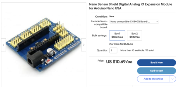
Question about power? I was thinking of this board, because it has a power input jack. I see you don't have that so how are you powering yours?
 

Attachments

  • Screen Shot 2023-03-11 at 1.46.35 PM.png
    Screen Shot 2023-03-11 at 1.46.35 PM.png
    876.2 KB · Views: 111

ic-racer

Member
Joined
Feb 25, 2007
Messages
16,480
Location
USA
Format
Multi Format
I'm going to add a calibration factor to the code. I know for my existing Laser/Photodiode tester the calibration factor is the same across all speeds. The issue (with my present shutter tester) is the photodiode turns ON too soon and turns OFF too late as the shutter slit passes. This would cause the shutter speed to indicate slower than reality or estimate a wider slit opening.

I used to program in C++ and get this, I had a Mac with two slots (no hard drive). To compile, I had to swap disks in and out of the slots. So it has been a while since I coded anythng...

A few years ago I wanted to show my kids some of my programs, but the Mac SE30 I still have has a hard disk and none of my software is on it. Don't know where all my floppies are, probably are no good anyway.
 
Last edited:
OP
OP

Niglyn

Member
Joined
Feb 26, 2022
Messages
402
Location
Surrey, UK
Format
Analog
Question about power? I was thinking of this board, because it has a power input jack. I see you don't have that so how are you powering yours?

Hi,
looks like that board, you can plug in a 9V or maybe 12V power supply & the board has a voltage regulator.

I just connect mine up to the computer via the USB socket.

For stand alone, just use a phone charger with the right lead to plug into the USB socket.
 
OP
OP

Niglyn

Member
Joined
Feb 26, 2022
Messages
402
Location
Surrey, UK
Format
Analog
I'm going to add a calibration factor to the code. I know for my existing Laser/Photodiode tester the calibration factor is the same across all speeds. The issue (with my present shutter tester) is the photodiode turns ON too soon and turns OFF too late as the shutter slit passes. This would cause the shutter speed to indicate slower than reality or estimate a wider slit opening.

I used to program in C++ and get this, I had a Mac with two slots (no hard drive). To compile, I had to swap disks in and out of the slots. So it has been a while since I coded anythng...

A few years ago I wanted to show my kids some of my programs, but the Mac SE30 I still have has a hard disk and none of my software is on it. Don't know where all my floppies are, probably are no good anyway.

What do you use to check the calibration? Think you maybe chasing your tail with this one.
 
Photrio.com contains affiliate links to products. We may receive a commission for purchases made through these links.
To read our full affiliate disclosure statement please click Here.

PHOTRIO PARTNERS EQUALLY FUNDING OUR COMMUNITY:


Ilford ADOX Freestyle Photographic Stearman Press Weldon Color Lab Blue Moon Camera & Machine
Top Bottom