Build a shutter tester for Focal Plane shutters - Cheap, Easy & it Works

On The Mound

A
On The Mound

  • 5
  • 3
  • 84
Finn Slough-Bouquet

A
Finn Slough-Bouquet

  • 0
  • 1
  • 50
Table Rock and the Chimneys

A
Table Rock and the Chimneys

  • 4
  • 0
  • 120
Jizo

D
Jizo

  • 4
  • 1
  • 100
Top Floor Fun

A
Top Floor Fun

  • 0
  • 0
  • 86

Recent Classifieds

Forum statistics

Threads
197,412
Messages
2,758,610
Members
99,490
Latest member
ersatz
Recent bookmarks
0

Grenversity

Member
Joined
Mar 17, 2024
Messages
7
Location
UK
Format
35mm
Just built the tester and I wanna say thank you for the detailed explanations.

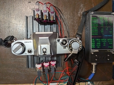
Here are my results for a Canon AV-1. As expected, there are a lot of inconsistencies at higher shutter speeds. Am I reading the results correctly by saying that the first curtain is slowing down/ second curtain is speeding up and thus resulting in laser 2 being wayyyy off and at maximum speeds, even closed at 1/1000. The AV-1 is aperture priority so I had to get these results by putting my phone flash in front of the camera and taking the picture at the shutter speed I wanted, which means the numbers are probably off since I couldn't set them.


1711143401007.png


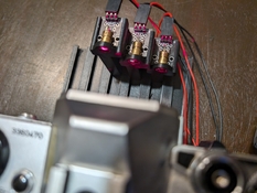
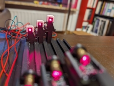
This was my first attempt at assemblying it. Since then I've added a small wood panel with smaller holes so the laser size is smaller and added a base so everything stays aligned.

141729C0-FC6A-4FB7-9D58-9135304216AD.JPG
 
OP
OP

Niglyn

Member
Joined
Feb 26, 2022
Messages
402
Location
Surrey, UK
Format
Analog
Hi,
Most interesting readings.
Curtain 2 remains a very consistent speed, but then looses it at 1/1000.
Curtain 1 seems ok until 1/250s when it starts to slow down. Bizzare why it only slows at higher speeds.
At 1/1000s I would guess first curtain is so slow that second curtain has caught up with it & is giving shutter blanking, hence no 1/1000s reading for laser 2.
Are you running the latest firmware version, 3_1_3 ?
 

Grenversity

Member
Joined
Mar 17, 2024
Messages
7
Location
UK
Format
35mm
Hi,
Most interesting readings.
Curtain 2 remains a very consistent speed, but then looses it at 1/1000.
Curtain 1 seems ok until 1/250s when it starts to slow down. Bizzare why it only slows at higher speeds.
At 1/1000s I would guess first curtain is so slow that second curtain has caught up with it & is giving shutter blanking, hence no 1/1000s reading for laser 2.
Are you running the latest firmware version, 3_1_3 ?

Arduino with the 3_1_3 software. I probably have like 4-5 readings for each speed. They are all constant in how bizarre they are; I could never get a reading for laser 2 at 1/1000.

This is a photo which was probably taken at 1/500-1/1000. The dark side is on the right side of the film.

untitled-17-jpg.365732

My understanding before was that the issue was happening at the beginning of the shutter opening sequence since the problem was on the right side of the film, but that seems to not align with the readings. Not sure if there is a problem with my set up or I'm misunderstanding the issues with my camera.
 
OP
OP

Niglyn

Member
Joined
Feb 26, 2022
Messages
402
Location
Surrey, UK
Format
Analog
Right side of the film from in front, or behind the camera?
Can you post the strip of negatives (backlit) so we can see the film edge markings.
Also do you have a landscape photo showing the error?

The image is projected upside down and back to front onto a negative, so top is bottom, left is right.
Assuming you rotated the camera anti-clockwise when taking a portrait photo, then the blanking is at the bottom, so reversed, would be at the top, so indeed at the beginning of the exposure, not the end.

You could use the tester in single laser mode. Cover laser 2 sensor so it does not get triggered.
Align laser one at the left edge of the film gate and take a photo, see if you get an exposure reading.
Now align the laser with the right edge of the film gate & repeat. This will prove which side the shutter blanking is occurring.

Greenwich Navy College?
 

Grenversity

Member
Joined
Mar 17, 2024
Messages
7
Location
UK
Format
35mm
Oh, I didn't realise the image is reversed both axis onto the film. That makes more sense now, the issue is on the right side of the imagine, so the left side of the film when shooting. Here's a landscape, from Greenwich as well.

Untitled-9.png


Guess I need to find a way to CLA my camera. Thanks again for the detailed instructions, it was a lot of fun building and troubleshooting this build
 
OP
OP

Niglyn

Member
Joined
Feb 26, 2022
Messages
402
Location
Surrey, UK
Format
Analog
Oh, I didn't realise the image is reversed both axis onto the film. That makes more sense now, the issue is on the right side of the imagine, so the left side of the film when shooting. Here's a landscape, from Greenwich as well.

View attachment 366244


Guess I need to find a way to CLA my camera. Thanks again for the detailed instructions, it was a lot of fun building and troubleshooting this build

Thought it was Greenwich.

Learncamerarepair.com does not have the service guide, but does have a journal referencing the AV-1 $2.58 per download.

Personally, unless scrap anyway, I would not take the camera apart, but find a good canon service tech.

The learn camera repair facebook group might be able to offer an opinion on cause and recommend a UK service centre. You could always call Fixation in SE London, over Tower Bridge way.
 
OP
OP

Niglyn

Member
Joined
Feb 26, 2022
Messages
402
Location
Surrey, UK
Format
Analog
I have finally got round to putting my shutter tester in a box! Only took three years :surprised:)

I needed to use a bigger box to allow the LCD to also fit.

If using the TFT screen only, the smaller box (see my Developing Timer or Trigger / Splash Timer) would look better.

Included are extra buttons & an encoder knob. Not currently used, but I may add functionality for them later.

Second photo shows the new sensor head (below the camera & still covered in masking tape) which fits into the camera film gate and does away with the blocks of wood (or Lego) and the Lasers.

The Lasers work fine if the sensors/Lasers are aligned horizontally, but if using the diagonal pattern to use with both horizontal & vertical shutters, alignment becomes a pain.

It is simply the sensors (which need filing to remove part of housing), taken from the module and fitted into a little box. As there is no room for the module (which also contains a resister & capacitor) these have to be soldered directly to the legs of the sensor.

Light is provided from a cheap LED light box (shown below the sensor box). Due to it using PWM, it must be turned to full brightness, else the shutter Tester is so fast, it detects the PWM pulses.

The one issue I have found, is that the Shutter Tester now records one shutter bounce. I assume this is due to the PWM LEDs

Currently, the new sensor head is hard wired & all the wires for this & the light-meter can be seen spilling out from the box. I'm waiting on some connectors to arrive (and a smaller sensor box) then I will add a parts & build guide to Github.


20240407_130111.jpg


20240407_130136.jpg
 
Last edited:

Michael Huang

Member
Joined
Apr 18, 2024
Messages
1
Location
Suzhou, China
Format
35mm

hi, the first post in the forum, first of all , appreciate Niglyn share the procedure and detailed guideline. Copied 2 sets, one for myself and another one for a net friend with 0 charged. all material from Taobao China and estimated cost 15~18 USD .most high price is TFT, if use LCD will reduce the cost <15USD. 2 set looks different result at right side of film window(sensor 1) when speed goes to 1/1000, i assume the tolerance from hole size. I use a black tape and punch a hole with needle. I am think about to drill 3 hole on machine may get accurate size and position.


IMG_9764.JPG
IMG_0024.JPG
 
OP
OP

Niglyn

Member
Joined
Feb 26, 2022
Messages
402
Location
Surrey, UK
Format
Analog
HI,
3d printed parts look really good.

You will find from older cameras, how inaccurate they are and how exposure will vary from one side of the photo to the other.

It will drive you mad if trying to get the speeds 100%.
Then the weather will change, the grease harden or soften & the speeds will be different again anyway :surprised:)
Providing the speeds are within the iso tolerance (post of these further up) that is good enough.

The speed algorithm uses the curtain travel as part of the calculation and assumes a linear speed. If there are curtain issues, then the calculated speed can show wild results.

The sensors are 1mm and this is the figure used in the algorithm to calculate shutter speed. Masks should not be necessary and if not made accurately, will cause issues.
 

jasonliu

Member
Joined
Nov 22, 2023
Messages
2
Location
Taiwan
Format
35mm
thanks for your invention!I wanna try this one,and all of the materials just arrived.i can't message you to get the ESP code because I'm new user of photrio😢
 
OP
OP

Niglyn

Member
Joined
Feb 26, 2022
Messages
402
Location
Surrey, UK
Format
Analog

jasonliu

Member
Joined
Nov 22, 2023
Messages
2
Location
Taiwan
Format
35mm
Fear not, all the firmware is on Githib


thank you so much for helping! I've done the wiring and flashed the firmware to ESP 32 successfully! Now all I have to do is build a case for it!😀
 

040medien

Member
Joined
Jun 2, 2024
Messages
2
Location
Hamburg
Format
Medium Format
Also built my own shutter tester. Thank you for the software and the documentation @Niglyn!

I designed my own enclosure and also a mount system for the sensors and lasers which uses separate tracks so I can set them up for 35mm and 120 (6X7) cameras. If there is interest, I can upload the files to Printables.

Note that in my case I had to select baud rate 460800 to use the serial console.

I noticed too late that in my design the sensors are facing the wrong way. But I liked that the cables faced outward, so I just printed a few white "caps" that reflect the light back to the sensor. Works a treat. On the side facing the camera, there is a 3 mm hole that the laser has to hit. I had to bend the laser modules a bit, but in the end it worked fine.

I noticed that with version 3.0.8.7 my buttons didn't work at all, but when I flashed 3.0.8.6 they worked fine.

Have you considered uploading the latest source code to github as well?
 

Attachments

  • PXL_20240602_194639459.jpg
    PXL_20240602_194639459.jpg
    871.7 KB · Views: 43
  • PXL_20240602_194705151.jpg
    PXL_20240602_194705151.jpg
    348.1 KB · Views: 42
  • PXL_20240602_194719610.jpg
    PXL_20240602_194719610.jpg
    275.4 KB · Views: 40
OP
OP

Niglyn

Member
Joined
Feb 26, 2022
Messages
402
Location
Surrey, UK
Format
Analog
Hi 040mediien,

Thanks for posting the photos, looks good. Yes please publish you 3d printer files, I can also put them on Github & Instructables.

I have no idea why buttons do not work on 3.0.8.7. Was it all of the buttons?
I don't have a copy of 3.0.8.7 source code, as I overwrote it with 3.0.8.8.

Button 5 is added, this is only for the LED matrix, so only needed if it is fitted. Button 5 also operates as the Flash button on the MCU32 board, so can be used rather than having to open the case when flashing firmware.

The latest version 3.0.8.9 will be along soon. It adds more curtain speed information, to the PC screen only. I might also display the raw shutter speeds, before computation to remove sensor width. Whilst this will show an under exposure, it can be useful if the shutter curtains are very erratic.

I don't post the source code for two reasons. There are a number of additional libraries used to keep my code organised so this complicates things for users having to add these additional files. I use a cunning algorithm to sole the issue of sensor width, to give accurate shutter speed (exposure) readings. Designers of other testers are unwilling to divulge how they solve the problem (if they do) so I'm not going to share my method.
 

040medien

Member
Joined
Jun 2, 2024
Messages
2
Location
Hamburg
Format
Medium Format
None of the buttons worked in 3.0.8.7. Bummer that you don't keep a record of old code versions on github, that would make it easier to fix regressions - including with the help of contributors like me.

I'm certain a lot of clever engineering went into the project and it's your call what you do with it. As you can see in my github account (same user name, I've contributed to a fair few of open source projects over the years - both with code and 3d models, e.g. for the photon light meter project. I'd say the power of open source has to be experienced, so I'm not trying to convince you - just sharing my point of view.

Sharing the code doesn't prevent you from sharing the binaries as well. Even if I would have not bothered to build the code, I might have been able to identify what caused the issue with the buttons. That would have saved me re-checking my whole wiring before finally testing an earlier build to find out it was a software issue.

As to not sharing because others aren't: I had searched for 3D printing files for this project and couldn't - even though some people here have clearly created some. I decided to share my files with the hope that others might contribute theirs.

You can find the 3D printing files here. I provided them unter a share-alike license, so if you should consider to publish your source code, I'd be happy to create a pull request on github to include them in your project. Otherwise, please only link to my Printables page.
 
OP
OP

Niglyn

Member
Joined
Feb 26, 2022
Messages
402
Location
Surrey, UK
Format
Analog
Hi 040medien,
It was just an error on my part that I started editing 3.0.8.7 before saving it, so it became 3.0.8.8 although there were no changes to the existing buttons, so can't understand why it does not work. I have loaded 3.0.8.8 and that works fine.

Will upload 3.0.8.8 to Github.

My projects are shared free of charge, both on Github & Instructables. The source code is compiled and shared as a bin file for direct flashing to the microcontroller.

I don't have a 3d printer, so there are no 3d files for this project. I was referring to other shutter tester project code, of which there are a multitude. Some share code, but there are a few others who sell their projects & say the purchased version accounts for the sensor issue.

I like your light-meter project. However, I have never used a Pi & looking at your github, I do not have a clue where to start. There seems to be a multitude of py files, which somehow must be assembled and uploaded to the pi board. Also the Pi stuff seems very expensive compared to the ESP32.
 
OP
OP

Niglyn

Member
Joined
Feb 26, 2022
Messages
402
Location
Surrey, UK
Format
Analog
I get worried when I see strange results posted from users of my shutter tester. My immediate thought is that there is a huge error in my code.

The post from Grenversity was one such post, but then I was vindicated and relieved when the photos were posted, clearly showing that the shutter tester was working perfectly & the camera did indeed have a capping issue. (I might write a specific routine to identify this)

So when I was trying to find any reason of the reported buttons not working (I can't) I was horrified to see the results below, showing an error with the flash testing routine. (bottom of the print-out) I don't often connect the flash socket, so rarely test this code routine.

So after checking & double checking & then testing other cameras. nope my code is good & the tester has again correctly identified a camera issue.

Capture.JPG
 

chuckroast

Subscriber
Joined
Jun 2, 2023
Messages
1,974
Location
All Over The Place
Format
Multi Format
I get worried when I see strange results posted from users of my shutter tester. My immediate thought is that there is a huge error in my code.

The post from Grenversity was one such post, but then I was vindicated and relieved when the photos were posted, clearly showing that the shutter tester was working perfectly & the camera did indeed have a capping issue. (I might write a specific routine to identify this)

So when I was trying to find any reason of the reported buttons not working (I can't) I was horrified to see the results below, showing an error with the flash testing routine. (bottom of the print-out) I don't often connect the flash socket, so rarely test this code routine.

So after checking & double checking & then testing other cameras. nope my code is good & the tester has again correctly identified a camera issue.

View attachment 371586

I've not examined your code, but are you debouncing your switches?
 
OP
OP

Niglyn

Member
Joined
Feb 26, 2022
Messages
402
Location
Surrey, UK
Format
Analog
I've not examined your code, but are you debouncing your switches?

Hi, yes that is a schoolboy error when moving to microcontrollers and getting several thousand 'button pushes' :surprised:)

Code looks for the signal to go low then ignores further reads (for speed)
 

pierre69

Member
Joined
Jun 11, 2024
Messages
4
Location
Lyon, France
Format
35mm
Hi all !
This is my first post in the forum.
It's my turn to present you my shutter tester.
First, thank you to Niglyn for the software and all the informations to built it.
I have tried to build it as small as possible. This have some advantages like the size but it also have some inconveniants. The wiring is very difficult.
The camera can be attached on the tester so you can do the tests really easily. I used a ball bearing linear guide (I had it in stock at work) so the lasers are constantly aligned with the sensors.
The lasers are located in the fixed part of the tester and the sensors in the mobile part.
The height of the part that support the camera can be adjusted.
I used a USB-C socket to power the tester and a switch to power it on.
I used 3.0.8.7 firmware. Do I need to update it to 3.0.8.8 ?
The tester works fine. I have only one problem. The ESP32 can't communicate with Arduino IDE. All the drivers are up to date. I have made a research on the internet and it appear that sometimes there is a problem with Windows 11. I will keeping looking what's wrong.

Here is the project done with SolidWorks and some pictures of my build.

Pierre

Shutter.JPG


IMG_2843.JPG


IMG_2837.JPG


IMG_2840.JPG


IMG_2841.JPG


IMG_2842.JPG
 
OP
OP

Niglyn

Member
Joined
Feb 26, 2022
Messages
402
Location
Surrey, UK
Format
Analog
Hi Pierre69,
Thanks for posting your build. It is nice for me to know people are building my projects. It makes the time needed to publish them worthwhile.

Would be great if you were willing to share your 3d stl files, together with details of pla used & parts needed to 3d print & additional parts you used.

You could save some wiring by not using the laser circuit boards. They do nothing than hold the laser. You can also buy the laser units on their own, just with thin wires attached. These do seem to be alittle higher powered, so I added a resister just to lower the current a bit.


The serial monitor function in Arduino IDE should work fine with the ESP32, the IDE is just being used as a dumb terminal. Pressing the reset on the ESP32 board should output a lot of boot info to the screen. The default baud rate for this is 115200


Not sure why your computer cannot see the ESP32 board. To use the Arduino IDE with ESP32 for programming, you have to add the ESP32 boards in -
file - preferences - Additional board manager URLs
then add this line -
Then in Tools - boards select ESP32 Dev Module
But as said, this is not needed just to see the output from the Shutter Tester on the PC screen.


The Shutter tester runs at 460800.
Can you see the ESP32 in device manager when plugged in? If the driver for the USB chip on the ESP32board is not correct, device manager will show an error in the UISB tab.

Any serial (USB) terminal emulator should work. I use Arduino IDE for convenience.

Glad 3.0.8.7 firmware is working for you. I had one report of buttons not working in this build, but could find no reason for it.
I just tweak the firmware about a bit to amuse myself. Nothing particularly better in .8

3.0.8.9 will be along soon. It adds additional camera diagnostics, some were already in the firmware as error checks, but now they print to the display.
These are things like slow or sticking curtains and shutter capping.

The flash diagnostics have also been upgraded to give better diagnostic output.

The PC screen now shows the raw sensor data, as well as the computed sensor data.
This shows & proves that errors occur when a) using a single sensor to measure shutter speed and without correction and
b) shutter testers will progressively under-read as shutter 'speed' increases - unless steps are taken to dynamically correct this error.

A constant cannot be used as slit width at a given shutter speed is not a constant. e,g a camera with flash sync speed of 1/30s will (should) have a slit width at 1/60s of 18mm. For a camera with flash sync speed of 1/60s the slit width at 125/s would be 18mm. Assuming horizontal shutter.

Shutter curtain travel speed is now also shown on the pc screen for both first half and second half of travel and overall travel speed.
This shows how much slower the curtain is over the first half, as it has to accelerate from 0.

I'm also thinking of adding the raw data and half-curtain time to the tft display. This however will mean some other data will need to be removed, to make space for it.

Happy for any ideas & suggestions, for upgrades, changes or additional functionality.
 
Last edited:

pierre69

Member
Joined
Jun 11, 2024
Messages
4
Location
Lyon, France
Format
35mm
@snusmumriken
Thank you !

@koraks
Thank you !
Yes, I have print this mounting studs with supports and they were removed at the end of the printing.

@Niglyn
I can share everything. All the files in every format. SolidWorks, STEP, IGES, STL. But before, I need to do some cleaning and organisation in the files because it has been design for myself. Were can I post them ?

Ok for the tip on the laser assembly !

I have understand the purpose of Arduino IDE. Just display the raw data.
My computer see the ESP32 Here is a screen shoot of the device manager. My compurter is in french.

Device manager.png


I have add the URL for the ESP32 board in Arduino IDE. I can select the right board "NodeMCU-32S" and the right Port COM. There is not problem here.
I think that the problem is the speed. I haven't got the possibility to select 460800.

Here is a screen shot of the Arduino IDE with the error display in red in the Serial Monitor.

Arduino IDE.png


I have to use more my tester to make suggestions. I think that it is nearly perfect.
 
Photrio.com contains affiliate links to products. We may receive a commission for purchases made through these links.
To read our full affiliate disclosure statement please click Here.

PHOTRIO PARTNERS EQUALLY FUNDING OUR COMMUNITY:


Ilford ADOX Freestyle Photographic Stearman Press Weldon Color Lab Blue Moon Camera & Machine
Top Bottom