Build a shutter tester for Focal Plane shutters - Cheap, Easy & it Works

On The Mound

A
On The Mound

  • 5
  • 3
  • 89
Finn Slough-Bouquet

A
Finn Slough-Bouquet

  • 0
  • 1
  • 51
Table Rock and the Chimneys

A
Table Rock and the Chimneys

  • 4
  • 0
  • 122
Jizo

D
Jizo

  • 4
  • 1
  • 102
Top Floor Fun

A
Top Floor Fun

  • 0
  • 0
  • 87

Recent Classifieds

Forum statistics

Threads
197,413
Messages
2,758,625
Members
99,491
Latest member
edwardSun
Recent bookmarks
0
OP
OP

Niglyn

Member
Joined
Feb 26, 2022
Messages
402
Location
Surrey, UK
Format
Analog
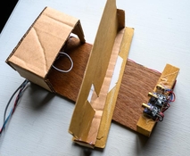
A question was asked as to why shutter speeds in my photos are so slow.
Well here is the answer.
This is my shutter-tester tester.
Rather than having to keep charging the shutter, I have a piece of card with a slot cut in it, which I push from one side to the other :surprised:)
I have a few variations, including one card with multiple slots, to simulate curtain bounce.
 

Attachments

  • untitled-81599.jpg
    untitled-81599.jpg
    95 KB · Views: 57
OP
OP

Niglyn

Member
Joined
Feb 26, 2022
Messages
402
Location
Surrey, UK
Format
Analog
Arduino Firmware Update Version 2
Hot on the heals of the ESP32 update, the new Arduino version is now live.

The Arduino Shutter Tester has always been popular, maybe because people are familiar with using Arduino & may already have the parts, or that it is a simpler build, who knows.

Arduino V2 Shutter Tester uses the same algorithm as ESP32, to show the corrected shutter speeds, mitigating sensor width.

Test data is displayed on the LCD and computer screen. PC shows additional data than cannot be displayed on the LCD.
Averages are displayed on LCD and PC screen, with PC screen additionally displaying the last 10 test results and running average.

Update & improvements, include,

Check-before-testing - to avoid erroneous readings when placing the camera in the tester.
Flicker warning - for pesky LED light interference.
Hung shutter.
curtain travel speeds
Shutter bounce.
advises when both curtains are fully open during an exposure - giving flash-sync speed.
Averages only updated with validated data.
One-Time passkey added.
Build and user guides updated.

Future updates,
Build-a-Box document detailing how to make an enclosure for the tester.
shutter drag warning.

As always, I welcome comments, feedback and ideas for additions & improvements.
 

ic-racer

Member
Joined
Feb 25, 2007
Messages
16,481
Location
USA
Format
Multi Format
Just curious on how your software reacts to capping and other crazy stuff. One unfortunate issue with the "Film Camera Tester" firmware is that if there is capping (the last sensor does not see any light) nothing happens. No warning or error. So, when one is repairing a camera that is really messed up (bounce, capping, slowing too much with the curtain brake, mirror not behaving, etc,) there is no feedback as to what is happening. The device has absolutely no response at all, as if the body cap is on. If you do fiddle with the camera's shutter, and get all the sensors to see light, the first reading (after the 'failed' attempts) is really messed up on the display.
 
OP
OP

Niglyn

Member
Joined
Feb 26, 2022
Messages
402
Location
Surrey, UK
Format
Analog
Just curious on how your software reacts to capping and other crazy stuff. One unfortunate issue with the "Film Camera Tester" firmware is that if there is capping (the last sensor does not see any light) nothing happens. No warning or error. So, when one is repairing a camera that is really messed up (bounce, capping, slowing too much with the curtain brake, mirror not behaving, etc,) there is no feedback as to what is happening. The device has absolutely no response at all, as if the body cap is on. If you do fiddle with the camera's shutter, and get all the sensors to see light, the first reading (after the 'failed' attempts) is really messed up on the display.

Hi IC, thanks for the question.

Both versions (Arduino & ESP32) will not start a test until both sensors are blocked. This stops the erroneous readings and 'crazy stuff' when placing or removing a camera from the sensor frame. It also makes testing automatic, rather than having to press a 'start' button before every test.

Both versions have a maximum test time of 40 seconds (to allow for slow 32s testing) If the test has not completed during this time, the tester reports the error. This ensures the tester does not hang or have no response.

Similarly tests that are too fast, above 100Ms are reported as errors.

LED flicker interference can be an issue. Both versions now have LED flicker detection. Arduino only reports it during a test, but the more powerful ESP32 has additional detection & reports this in the Setup & Alignment utility.

Both versions detect shutter bounce. As soon as a valid test is seen, the tester just looks at the last sensor for one second and does nothing else. Bounces can be very fast, so full processor time is devoted to this.

Shutter blanking is detected in both versions. Arduino will see it as 'single sensor mode' so only sensor 1 test data will be displayed. The ESP32 version, with three sensors, can report shutter blanking more accurately.

Shutter drag/sticky curtain is now reported on the Arduino version (firmware on Github) It has a generous 1 second of travel time, before reporting as a specific error, but as curtain travel time is displayed, poor blind travel can be seen. The ESP32 version does not directly report shutter drag, instead giving a breakdown of curtain travel speed between each of the three sensors.

All data is validated, to ensure the display is not 'all messed up' failed data is nulled to avoid printing 'crazy stuff'. Only validated data us used to update the averages.

The ESP32 version has a much faster processor and more memory, both flash & ram, so collects and processes more data, from three sensors and the flash socket. This allows even better data validity checks and flash sync reporting.

There is no way (that I can think of) to detect or calibrate shutter braking with a shutter tester. I'm not aware of any tester that can do it. The only way I know of, is the old method of photographing a CRT tube


As you can see from the above, I have done everything I can possibly think of to make the tester function & work properly, without crazy stuff or hanging for no apparent reason. Always happy for feedback, ideas & suggestions for changes & improvements.


Here is a link, detailing single sensor testers and how awful they are. It also details the issue of sensor charatoristics influincing tests. My tester, of course, takes all of this into account to give proper accurate results.
They have another document with more in depth discussion of shutter testers, with sillyscope prints of these silly audio ones, showing how useless they are and also detailing better designed ones, but I am unable to find it at present.
 
OP
OP

Niglyn

Member
Joined
Feb 26, 2022
Messages
402
Location
Surrey, UK
Format
Analog
An extract from a kosmo foto article, detailing shutters and the testing of them. I agree with every word, which is why the multitude of DIY shutter testers available, either to purchase or make oneself, are simply inaccurate at higher speeds.

"The real switch of the sensor from light to dark comes not at the actual time of the curtain moving against the sensor, but at time when the actual light stream is reduced to what the sensor believes is dark, and sensor may have some inertia too. Also, the point of switching from light to dark is not the same as the point of switch from dark to light. So, sensors have their own characteristics that affect metering.

In this case we can reach an important conclusion: the shorter metered time, the more influence physical features of the device has on accuracy. In other words, the shorter the time measured, the more likely there will be an error in the metering".


And for leaf shutters, things get worse for leaf shutters

"And finally the case of the shortest speed. Leaves open – leaves close. No delay. Shutter did not stay in the fully opened position. And in this case the result of metering is not dependent on the shutter! The result is dependent on device characteristics only! In Picture 5 I show three possible levels of the switching sensor: L1, L2, L3. Using those levels we can get three values of the metered time t1, t2, t3. And all the values will be correct. But they will reflect not the shutter speed, but the internal setting of the metering device".

Screenshot-2020-12-09-at-09.16.46.png


"And now some final conclusions:

  • The metered value always contains an error.
  • With a faster shutter speed, the margin of error in the metered value is greater.
  • Never use as the correct value the metered value based on the fastest shutter speed, especially for leaf-shutter cameras"

Thank heavens we have my Shutter Tester, cheap, simple and the most important factor:-
It works!

Errors detailed above are mathematically computed in my shutter tester and the results shown are the calculated exposure values, thus giving an accurate result.

I suppose I really should come up with a proper name for my shutter tester.
suggestions please......
 

OAPOli

Member
Joined
Sep 26, 2022
Messages
621
Location
Toronto
Format
Medium Format
@Niglyn I agree that in order to compute the higher speeds accurately, one needs to take into account the raise and fall times of the light signal onto the sensor.

Are you saying that one can measure the time-dependent signal from the laser module receptor? I thought its output was binary...
 
Last edited:
OP
OP

Niglyn

Member
Joined
Feb 26, 2022
Messages
402
Location
Surrey, UK
Format
Analog
@Niglyn I agree that in order to compute the higher speeds accurately, one needs to take into account the raise and fall times of the light signal onto the sensor.

Are you saying that you can measure the time-dependent signal from the laser module receptor? I thought the output was binary...

Hi OAPOli,
My tester computes the correct exposure using the (up to) twelve different readings it takes during a shutter test cycle.

It does not simply apply a calibration constant as the speeds get faster. To do this would give inaccurate results.
The ESP32 has a duel core processor, so this allows mundane tasks to run there, leaving the main fast core to get on with other things.
 

ic-racer

Member
Joined
Feb 25, 2007
Messages
16,481
Location
USA
Format
Multi Format
I have some extra Adruino boards, I'll probably boot up one with the firmware for flexibility. For example, testing 4x5" FP shutters. I saw an article in an old SPT journal where the shutter can be placed up against the light source and slit mask (narrower than the shutter's smallest slit) placed over the light source. Then the sensor is placed in front of the lens.
 

OAPOli

Member
Joined
Sep 26, 2022
Messages
621
Location
Toronto
Format
Medium Format
Hi OAPOli,
My tester computes the correct exposure using the (up to) twelve different readings it takes during a shutter test cycle.

It does not simply apply a calibration constant as the speeds get faster. To do this would give inaccurate results.
The ESP32 has a duel core processor, so this allows mundane tasks to run there, leaving the main fast core to get on with other things.

Sounds good. The article you referred to mentions the raise/fall timings so I thought your tester collected that information.
 
OP
OP

Niglyn

Member
Joined
Feb 26, 2022
Messages
402
Location
Surrey, UK
Format
Analog
Sounds good. The article you referred to mentions the raise/fall timings so I thought your tester collected that information.

Even using an analogue device like a LDR, one could watch for the exact moment, the resistance decreased, meaning light was seen, and again the moment the resistance started to fall, showing light was being lost, by the curtain starting to cover it. So even an LDR with have a rise point and a fall point.

The rise point and the fall point on the sensor width are not the same, this gives 'width' to the sensor, thus the recorded errors.

Modern photo-transistors switch very fast, so whilst in the 60s & 70s shutter testers would have had LDRs, there is no benefit in using them compared to a modern photo-transistor. Of course any sensor, whether it be an LDR or transistor, has width, which must be correctly calibrated for.

Often infrared beams are used for positioning robotic machinery, including CNC. The same issue of sensor width arises. Here, you run the machine back until the beam is just covered, tripping the sensor, then carefully move it forward again, until the sensor trips open, thus giving repeatability. Not that I am giving any secrets away about how my (up to) twelve separate readings & algorithm work :surprised:)

Having said the above and the chase for ultimate accuracy. One must remember that these focal-plane shutters, being operated by springs, wound up to a random strength, are horribly inaccurate to start with. Even some of the better brands admitted the 1/1000s speed was not attainable.

What is better, is to have an even exposure across the film, rather than a spot-on shutter speed. Film, other than colour transparency has a wide latitude for exposure & even when using transparency (I loved the 3M transparency film, back when they made it) does one really meter the highlights, shadows & everywhere in between, to ensure the levels fall within the f-stop range of the film?
 
OP
OP

Niglyn

Member
Joined
Feb 26, 2022
Messages
402
Location
Surrey, UK
Format
Analog
I have some extra Adruino boards, I'll probably boot up one with the firmware for flexibility. For example, testing 4x5" FP shutters. I saw an article in an old SPT journal where the shutter can be placed up against the light source and slit mask (narrower than the shutter's smallest slit) placed over the light source. Then the sensor is placed in front of the lens.

Hi, what this is doing is restricting sensor width, which we know is the main issue causing measuring inaccuracy.
I had a look at your shutter tester schematics. Unfortunately the pin wiring does not match that of mine, so my firmware would not directly run on it.
It would be possible to make an adaptor module, which moves the pin positions, or use dupont wires to plug it up.

The only issue would be the light source, which requires a PWM signal (unless it also has a straight on/off switch or can be wired to a constant voltage)

I tried to add PWM light control to my ESP32 tester, to drive a constant current power source. Unfortunately. rather than the parts that I had ordered, lenses, heatsinks, COBs, drivers etc, turning up, a job-lot of expensive RGB lighting equipment arrived, which despite the expense, is of no use to me.
(Actually PWM control is added, I just don't publicise how to connect it)

The guy in China wants me to send the incorrect parts back, but postage is way too expensive. I think if I re-ordered the parts I need, the supplier would just keep my money. (Chinese state subsidise export postage, so they can dominate the world, but they do not subsidise returns)
 
OP
OP

Niglyn

Member
Joined
Feb 26, 2022
Messages
402
Location
Surrey, UK
Format
Analog
So here is an interesting screen shot from The Shutter Tester.

I have been trying to find a suitable LED light, that can be controlled by PWM, but crucially is then driven by controlled current, so there is no PWM flickering.

Turning the LED light on & then off, all sensors are seen and blocked at exactly the same time.

This proves that there is no jitter or lag in the code, as each sensor state changes.

Capture.JPG
 
OP
OP

Niglyn

Member
Joined
Feb 26, 2022
Messages
402
Location
Surrey, UK
Format
Analog
Hi everyone,

I stumbled upon Alin's three part youtube of his building The shutter Tester.

It is based on the slightly older version & shows how users can adapt or change the basic design for their own needs.

Many (hopefully all) of the issues found by Alin have been addressed in the latest build, user guides and firmware.
These include, neater wiring, positioning the USB connector to the edge of the box, updated display, giving the option of detailed or simplified view.


Picture1.jpg


Desmondo

Member
Joined
Dec 12, 2024
Messages
2
Location
Leeds
Format
35mm
Hi, as requested, I'm embarking on building this thing and saying hi. Currently got as far as ordering all the bits in the list, now waiting for them to arrive. Very excited about it, looks like a lot of work has gone in to it, so very generous of Niglyn to share it in the first place and others to contribute. Anyway, thats it for now, hopefully I'll be back soon with a finished build, or a bunch of problems. One of the two :smile:
 
OP
OP

Niglyn

Member
Joined
Feb 26, 2022
Messages
402
Location
Surrey, UK
Format
Analog
Hi, as requested, I'm embarking on building this thing and saying hi. Currently got as far as ordering all the bits in the list, now waiting for them to arrive. Very excited about it, looks like a lot of work has gone in to it, so very generous of Niglyn to share it in the first place and others to contribute. Anyway, thats it for now, hopefully I'll be back soon with a finished build, or a bunch of problems. One of the two :smile:

Hi Desmondo, welcome to the thread. Hopefully you will find the build guides will take you through the build ok. Feel free to ask any questions if anything is not clear.

I built a complete new V4 tester to enable me to update the build documents and take new photographs, so hopefully everything should be correct.

Please report back any mistakes or anything which is not clear, so I can correct and update them where required.
 

Desmondo

Member
Joined
Dec 12, 2024
Messages
2
Location
Leeds
Format
35mm
Hi Desmondo, welcome to the thread. Hopefully you will find the build guides will take you through the build ok. Feel free to ask any questions if anything is not clear.

I built a complete new V4 tester to enable me to update the build documents and take new photographs, so hopefully everything should be correct.

Please report back any mistakes or anything which is not clear, so I can correct and update them where required.

Thank you, I can't wait to get started and will let you know how I get on!
 
OP
OP

Niglyn

Member
Joined
Feb 26, 2022
Messages
402
Location
Surrey, UK
Format
Analog
Hi Everyone,

The video below is doing the rounds, a £25k record player pre-amplifier was sent to the manufacturer to repair. Owner did not like the price quoted, so sent it to Mend it Mark instead. Manufacturer did not like the video & got it removed from youtube.

The Streisand effect is now taking over :surprised:)

Do you think the build quality of this £25k product is any better than than our build of The Shutter Tester?

Was happy to see a £25k product also uses hot-glue :surprised:)


joemcc

Member
Joined
Dec 18, 2024
Messages
1
Location
Australia
Format
35mm
Hi Niglyn, thanks for your work on this project. I'd like to build it and have the hardware, but it's my first time on Photrio, so I can't message to request the passkey due to not enough posts. Are you able to help me out? Thanks in advance.
 
OP
OP

Niglyn

Member
Joined
Feb 26, 2022
Messages
402
Location
Surrey, UK
Format
Analog
Hi Niglyn, thanks for your work on this project. I'd like to build it and have the hardware, but it's my first time on Photrio, so I can't message to request the passkey due to not enough posts. Are you able to help me out? Thanks in advance.

HI, yes no problem.

You need to build The Shutter Tester and flash the firmware before I can give the passkey.

Each passkey is super unique, using a sneaky algorithm with built in electronic counter-measures for those that try to crack it :surprised:)
The Shutter Tester will generate it's own unique Authorisation Key, which will be displayed on the screen.
DM this to me when you are ready.

I will send you a DM, which I think will then mean you can DM me in return.
 
OP
OP

Niglyn

Member
Joined
Feb 26, 2022
Messages
402
Location
Surrey, UK
Format
Analog
Thanks Koraks.

As a minimum, the ESP32 module requires the firmware flashing and the rotary encoder & blue button connected before a User Key can be entered.

The user will also need to either use the PC screen (using Arduino IDE) or connect the TFT display, else they cannot see what they are doing :surprised:)


For the Arduino version, the User Key is entered by typing this directly into the PC screen using Arduino IDE, so a bare Nano board is all that is required.
 

Spachal

Member
Joined
Dec 3, 2024
Messages
18
Location
Czech Republic
Format
Medium Format
First of all, Christmas greetings from Czech Rep. and a big thank you to the author, Niglyn, for all the work done!
This thread has forced me to register here on the forum, this project is very well done and documented. I am gradually building a shutter speed meter and would like to contribute a little to the development. I have a professional 3D printer available and an idea in my head how to create a universal design. Once (if) I manage to assemble it all successfully, I will of course share the solution and STL files.

I have bought everything I need on AE, I 'just' need to assemble and activate it all :]. And I have a few questions and notes:
First of all, please Niglyn, PM me, I need the code for hwid 65757120, thank you!

A few points that could make the initial installation easier for people:
  • it is not necessary to install Arduino IDE just for the console (in the case of the ESP32 variant), a simple Putty program is sufficient. Set the COM port according to what the ESP will have in Device Manager and the speed is 115200bps
  • for installation, only ESP32 and encoder are needed
  • if you are looking for a blue button in the diagram like I did, it is part of the encoder, the rotary knob is also a push button :]
And I have a question regarding the construction of the meter I would like to build. It mainly concerns universality for both 35mm and 120mm film medium format cameras.
For 35mm cameras, near everything is clear, there are three sensors, horizontal spacing 32mm, vertical 20mm (or set the spacing in Setup). But how to solve the measurement in the case of 120mm film cameras? I thought of adding two more sensors (and lasers), there would be 5 in total, the center sensor would be common. Either they would all be connected, or I would add a 35/120 switch to the construction. Is this a reasonable solution, or are the same sensors sufficient for measuring 120mm shutters as for film?

Is there any reason to be able to rotate the lasers and sensors either vertically or horizontally, depending on the type of shutter? I would rather have the sensor placement fixed, but if it is appropriate, I will adapt the construction to it.

And I have a comment regarding the placement of sensors and lasers, I think it is a very good idea to illuminate the lasers 'from behind' the shutter and have the sensors placed on the lens mount side. The reason is safety, after all, it is not good to see laser beams in the viewfinder. In the pictures, I have also seen the opposite placement ..

I have a lot more questions, but many of them will probably be answered during the meter's construction and testing. Or I can ask you more experienced people again.
I have a lot of analog cameras, mostly 35mm film, but I mainly need to test medium format (Kiev 60/80/88, PSix..). And I can also help with testing very fast shutters (Nikon FM2 - 1/4000s), leaf shutter lenses, vertical and horizontal shutters, etc.
 
Photrio.com contains affiliate links to products. We may receive a commission for purchases made through these links.
To read our full affiliate disclosure statement please click Here.

PHOTRIO PARTNERS EQUALLY FUNDING OUR COMMUNITY:


Ilford ADOX Freestyle Photographic Stearman Press Weldon Color Lab Blue Moon Camera & Machine
Top Bottom