First of all, please Niglyn, PM me, I need the code for hwid 65757120, thank you!
Welcome aboard @Spachal! Note that you can now initiate private conversations, so you can reach out to @Nyglin autonomously.


First of all, please Niglyn, PM me, I need the code for hwid 65757120, thank you!
 )
)Many thanks to @Niglyn for creating an excellent guide on GitHub and a comprehensive kit list and instructions. Installation on the Arduino went great. Genuinely quite easy
Can you kindly PM me a passcode if you don't mind?
Happy to hear you found it easy to build. Many people are not familiar with microcontrollers or flashing firmware to them., so I have tried to explain things in a step-by-step process.
'Block of wood' sensor frame is quick & easy to build, will get you up & running quickly. Best to build a separate frame for horizontal and vertical shutters.
I found making a universal sensor frame, where the sensors/Lasers are arranged diagonally, is really fiddly to use, as the camera has to be aligned in both planes.
How did you hear about The shutter Tester? Would be interesting to know if it is via Instructables/Github/Photrio or other postings on the web.
)Hello in the New Year, I thought I had somehow broken this thread ;] ..
In any case, I wanted to ask if anyone has already dealt with micro-adjustment of laser modules, how to precisely aim them at sensors.
I have two solutions in mind, but both are quite complex, and it's possible that there's a relatively simple solution, but I just can't see it. .If anyone has already solved this (by that I don't mean fixing the laser in place and maybe gluing it, but really the possibility of fine-tuning the beam position), please let me know. Thank you!
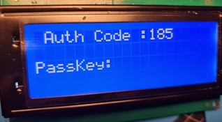
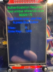
)Hello to all and thanks to Niglyn for this project. I think -- think! -- I'm ready to load the shutter speed program onto the ESP32. Is this the point at which I need a code for the software? Thanks!View attachment 388396
I often get questions on why a camera shutter is not showing the correct speeds.
Sometimes people even grumble that The Shutter Tester is not working properly!! The audacity
Here is a page from a Nikon service manual, showing the tolerances.
View attachment 387935
Hello in the New Year, I thought I had somehow broken this thread ;] ..
In any case, I wanted to ask if anyone has already dealt with micro-adjustment of laser modules, how to precisely aim them at sensors.
I have two solutions in mind, but both are quite complex, and it's possible that there's a relatively simple solution, but I just can't see it. .If anyone has already solved this (by that I don't mean fixing the laser in place and maybe gluing it, but really the possibility of fine-tuning the beam position), please let me know. Thank you!
And here it is waiting for the code:
Hi, sorry, only just seen this post & did not get email notification of your post #594.Which is my way of politely but possibly not clearly asking Niglyn for a code. Thanks!
My post #178 in this thread might help you? It doesn’t deal with micro-adjustment, but it sure makes alignment easy.
Hi Jonathan, thanks, that could help, thank you!
I intend to create a separate sensor module that is independent of the measurement module. This would allow me to easily swap out the ESP32 for a breadboard with an Arduino and test the alignment of the lasers and sensors.
| Photrio.com contains affiliate links to products. We may receive a commission for purchases made through these links. To read our full affiliate disclosure statement please click Here. |
PHOTRIO PARTNERS EQUALLY FUNDING OUR COMMUNITY:  |