Build a shutter tester for Focal Plane shutters - Cheap, Easy & it Works

On The Mound

A
On The Mound

  • 5
  • 3
  • 84
Finn Slough-Bouquet

A
Finn Slough-Bouquet

  • 0
  • 1
  • 50
Table Rock and the Chimneys

A
Table Rock and the Chimneys

  • 4
  • 0
  • 120
Jizo

D
Jizo

  • 4
  • 1
  • 100
Top Floor Fun

A
Top Floor Fun

  • 0
  • 0
  • 86

Recent Classifieds

Forum statistics

Threads
197,412
Messages
2,758,610
Members
99,490
Latest member
ersatz
Recent bookmarks
0

tiasmaaa

Member
Joined
Mar 12, 2025
Messages
13
Location
Switzerland
Format
35mm
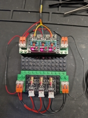
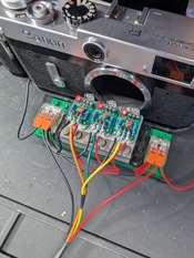
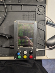
So I just did all the flashing things. Everything worked!

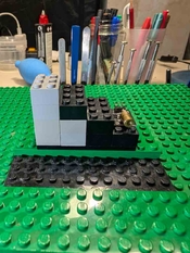
Now I'm trying to make a prototype for the lasers and im using Lego because I saw that in the pdf and thought it was a good idea.
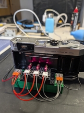
And actually I think it is, because I need to space the laser of 32cm horizontally and 20 vertically, and magic, 2 pieces of the black lego blocks built like that (see picture) is giving me exactly 32cm horizontally and 20 vertically. So ill try the version diagonally so I have both horizontal and vertical shutter testing.
One of the black lego block is 16x10mm. The laser modules are 16mm wide too. I think it fits pretty well.
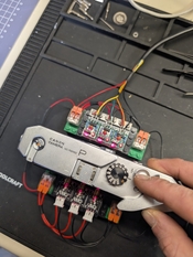
I didn't built the receiver Lego part at the moment. But I have a question. I'm wondering what is the best way to adjust the laser to get them pointing exactly in the receiver.
I will use hot glue as mentioned because I have the little time before glue is cold to adjust.
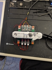
So I think I need to glue first the receiver in place. After that, I give power to the laser, then I'm hot gluing them and directly adjusting the laser for pointing in the little receiver ?
There's no risk of damaging the receiver ?

Can't wait to try this little tester!
 

Attachments

  • PXL_20250327_174300498.MP.jpg
    PXL_20250327_174300498.MP.jpg
    134.9 KB · Views: 22
Last edited:
OP
OP

Niglyn

Member
Joined
Feb 26, 2022
Messages
402
Location
Surrey, UK
Format
Analog
Hi Tiasmaaa,
The diagonal sensor format does not work well. The camera has to be aligned both horizontally and vertically, for it to work.

It is better to have two separate frames.
For example, horizontal only, you only need some spacers of different thicknesses to raise the camera to approximately centre height.
Then you only need to slide the camera left/right so the lasers are with the film gate.
With a diagonal configuration, the height has to be exact, as does the left/right.

As for aligning the sensors/lasers. Set the sensors up on 16mm centres (0, 16, 32mm) and then do the same with the lasers.
Often the lasers are only held on the board with the connecting wires, so they are easy to move slightly, so they point directly onto the sensor.
Hot-glue is ideal to then holed them in place.

The sensors will be damaged if they are connected incorrectly. The build documents show how the sensor should be plugged into the board.
More than one person has got this wrong and destroyed their sensors :surprised:(

You can power up the sensor boards before fitting the sensors, to ensure the red LED on the sensor board lights.
Then de-power and fit the sensors.

Happy tinkering :surprised:)
 

tiasmaaa

Member
Joined
Mar 12, 2025
Messages
13
Location
Switzerland
Format
35mm
hoy!

I took a bit of time because I had to re-order a socket usb C cable because the AliExpress one didn't work.

I listened to Niglyn's advice and aligned the lasers horizontally, not diagonally (I don't have a camera that works with a vertical shutter anyway). I used lego and hot glue to do this. I used connector blocks for the black and red wires. I also bent the sensors so that the little diode faces the outside of the board, which helps with the wiring.

I had initially inverted sensor 1 with sensor 2, and that's because I saw in the serial monitor (and not on the TFT screen) that it was telling me that the sensors were probably inverted! Thanks for the code!

Apart from that, I think everything's working fine. I did a full test with my new Canon P which will probably need some adjustments.
I put a .PDF file with all the data from the Canon P test, from 1sec to 1/1000sec.

From my analysis, 1sec and 1/2sec are pretty accurate. Perhaps the shutter curtain travel time could be a little faster?
From 1/4 to 1/30 are not at all correct. And here too, the shutter curtain travel time could probably be faster.
1/60 is pretty decent, 1/125 not so much, 1/250 not too bad, 1/500 pretty bad.
And I think 1/1000 is too fast and one of the lasers doesn't really react. There are the two different errors it gives me at the end of the PDF.

I still have a bit to learn about how exactly to understand all these results, and put them into practice.

But I'm already super happy that it works without any real problems, thanks again for this incredible work!
 

Attachments

  • PXL_20250401_153046450.MP.jpg
    PXL_20250401_153046450.MP.jpg
    1.4 MB · Views: 35
  • PXL_20250401_152523901.MP.jpg
    PXL_20250401_152523901.MP.jpg
    1.9 MB · Views: 31
  • PXL_20250401_152446763.MP.jpg
    PXL_20250401_152446763.MP.jpg
    1.3 MB · Views: 34
  • PXL_20250401_152353700.MP.jpg
    PXL_20250401_152353700.MP.jpg
    1.1 MB · Views: 30
  • PXL_20250401_152345016.MP.jpg
    PXL_20250401_152345016.MP.jpg
    1.4 MB · Views: 36
  • PXL_20250401_152336730.MP~2.jpg
    PXL_20250401_152336730.MP~2.jpg
    1.7 MB · Views: 37
  • SHUTTER TEST RESULTS FOR CANON P.pdf
    31.3 KB · Views: 15
OP
OP

Niglyn

Member
Joined
Feb 26, 2022
Messages
402
Location
Surrey, UK
Format
Analog
hoy!

I took a bit of time because I had to re-order a socket usb C cable because the AliExpress one didn't work.

I listened to Niglyn's advice and aligned the lasers horizontally, not diagonally (I don't have a camera that works with a vertical shutter anyway). I used lego and hot glue to do this. I used connector blocks for the black and red wires. I also bent the sensors so that the little diode faces the outside of the board, which helps with the wiring.

I had initially inverted sensor 1 with sensor 2, and that's because I saw in the serial monitor (and not on the TFT screen) that it was telling me that the sensors were probably inverted! Thanks for the code!

Apart from that, I think everything's working fine. I did a full test with my new Canon P which will probably need some adjustments.
I put a .PDF file with all the data from the Canon P test, from 1sec to 1/1000sec.

From my analysis, 1sec and 1/2sec are pretty accurate. Perhaps the shutter curtain travel time could be a little faster?
From 1/4 to 1/30 are not at all correct. And here too, the shutter curtain travel time could probably be faster.
1/60 is pretty decent, 1/125 not so much, 1/250 not too bad, 1/500 pretty bad.
And I think 1/1000 is too fast and one of the lasers doesn't really react. There are the two different errors it gives me at the end of the PDF.

I still have a bit to learn about how exactly to understand all these results, and put them into practice.

But I'm already super happy that it works without any real problems, thanks again for this incredible work!

Hi, happy it is all working for you.

Looking at your readings, it seems that the second curtain is running faster than the first.

At the higher speeds, The Shutter Tester is throwing up warnings that the first & Middle sensor (to be triggered) has triggered, but not the last.

This to me looks like shutter capping. The second blind catches up to the first, before the first has completed it's journey, thus the final part of the frame will not be exposed. *

I think I should add some plain test saying 'Shutter Capping'. Another update coming :surprised:)

I hope the wonky layout is your conversion to PDF and not my bad programming :surprised:)


-----------------------
*
Check your sensors are in the correct order. From behind the camera, sensor 1 should be on the right.

If the sensors operate in the reverse order, the firmware just swaps the readings, which is fine, but it can hurt ones brain if hardware Sensor 1 is reporting as firmware sensor 2.

It is strange that The Shutter Tester is reporting 2 & M triggered, but not 1. For Shutter capping it should be the other way around.

So either the sensors are reversed or at the start of the exposure, curtain 2 is also being released, thus blocking sensor 1, then the slit opens as the curtains travel, giving an exposure at sensor M and 2.

Please check the sensors & re-post the results.

You can also use Single Sensor Mode. Then you can manually test at different points along the film gate.

At least it proves all of the error checking & diagnostics inside The Shutter Tester are working :surprised:)
 

tiasmaaa

Member
Joined
Mar 12, 2025
Messages
13
Location
Switzerland
Format
35mm
Isn't the Sensor 2 which is triggering and not the others ?
Don't worry it's my PDF conversion that messed up the layout. Not from you :wink:.

I checked, and my sensor are correct, Sensor 1 is on the right while looking at the back of the camera (with laser pointing from the back to the shutter curtain).

I tried with Single Sensor at 1/1000, and only at the full left of the frame (again, looking from the back) the shutter tester gives me something, so where should work the Sensor 2 when using the 3 of them. That's why im asking if you're sure about the Sensor 1 and M triggering.
 

Spachal

Member
Joined
Dec 3, 2024
Messages
18
Location
Czech Republic
Format
Medium Format
Hi,
I haven't gotten around to the implementation yet (hopefully this month I'll have time to draw and print everything..), I have two questions following up on the discussion:
  • regarding the diagonal layout of sensors and lasers, is that not a good design proposal? I was counting on a universal design that would be suitable for both vertical and horizontal shutters, is this therefore an unsuitable way?
  • would it be possible (if this function is not already implemented) to include a function in the program that would test the functionality of the sensors and their correct wiring, for example by moving an obstacle (like a sheet of paper), so that it is clear that the sensors are wired correctly, are all functional and properly aligned?
 
OP
OP

Niglyn

Member
Joined
Feb 26, 2022
Messages
402
Location
Surrey, UK
Format
Analog
Isn't the Sensor 2 which is triggering and not the others ?
Don't worry it's my PDF conversion that messed up the layout. Not from you :wink:.

I checked, and my sensor are correct, Sensor 1 is on the right while looking at the back of the camera (with laser pointing from the back to the shutter curtain).

I tried with Single Sensor at 1/1000, and only at the full left of the frame (again, looking from the back) the shutter tester gives me something, so where should work the Sensor 2 when using the 3 of them. That's why im asking if you're sure about the Sensor 1 and M triggering.

Hi, I always worry when I see strange results posted, in case it is my code, but (again) it is showing The Shutter Tester is working correctly :surprised:)
but unfortunately your camera is not :surprised:(

You are getting shutter capping at the start of the frame, not, which is more common, at the end.

Capping is when both first and second curtain are overlapping as they travel across the film gate.

After curtain 1 is released, there should be a pause before the second curtain is released. This pause will control the slit width between the two curtains, thus control the exposure.

At flash sync speed e.g. 1/30s, the first curtain travels the full width of the film gate (so the whole frame is exposed) before the second curtain starts to close.
At 1/60s, the second curtain starts to close when the first curtain has travelled half way across the frame i.e 18mm
at 1/125s. it will be 9mm
at 1/250s it will be 4.5mm etc...

So the lightbulb moment here is that the shutter 'speed' never changes. It is the time between first and second curtain release and the slit width between the two curtains which determines exposure.

So in your case, at 1000/s second curtain is being released too early, before the first curtain has moved enough to create a gap between itself and the second curtain.

We know what the issue is with your camera, but there could ne a number of things causing the problem.
There is no easy fix. Cameras of this age require a full shutter service, to remove all of the old grease, lint etc that has build up over the years.
 
OP
OP

Niglyn

Member
Joined
Feb 26, 2022
Messages
402
Location
Surrey, UK
Format
Analog
Hi,
I haven't gotten around to the implementation yet (hopefully this month I'll have time to draw and print everything..), I have two questions following up on the discussion:
  • regarding the diagonal layout of sensors and lasers, is that not a good design proposal? I was counting on a universal design that would be suitable for both vertical and horizontal shutters, is this therefore an unsuitable way?
  • would it be possible (if this function is not already implemented) to include a function in the program that would test the functionality of the sensors and their correct wiring, for example by moving an obstacle (like a sheet of paper), so that it is clear that the sensors are wired correctly, are all functional and properly aligned?

Hi, If using diagonal Lasers, the camera has to be perfectly aligned both left-right and top-bottom to ensure all the Lasers are within the film gate.
It does work, just more fiddly to get the camera into the correct position.

If arranged just horizontally (for a horizontal shutter) the only critical alignment is left-right, The height can be close-enough-is-good-enough.

As for alignment, yes there is a whole alignment and diagnostics screen, see the user guide for details.

Moving a sheet of paper over the sensors. Cut slot of around 20mm into a piece of card, to simulate the curtain slit.
This is what I use when testing The Shutter Tester code. Easier than keep cocking a camera.
I have another card with two slots cut into it, to simulate shutter bounce.
 

tiasmaaa

Member
Joined
Mar 12, 2025
Messages
13
Location
Switzerland
Format
35mm
Hi, I always worry when I see strange results posted, in case it is my code, but (again) it is showing The Shutter Tester is working correctly :surprised:)
but unfortunately your camera is not :surprised:(

You are getting shutter capping at the start of the frame, not, which is more common, at the end.

Capping is when both first and second curtain are overlapping as they travel across the film gate.

After curtain 1 is released, there should be a pause before the second curtain is released. This pause will control the slit width between the two curtains, thus control the exposure.

At flash sync speed e.g. 1/30s, the first curtain travels the full width of the film gate (so the whole frame is exposed) before the second curtain starts to close.
At 1/60s, the second curtain starts to close when the first curtain has travelled half way across the frame i.e 18mm
at 1/125s. it will be 9mm
at 1/250s it will be 4.5mm etc...

So the lightbulb moment here is that the shutter 'speed' never changes. It is the time between first and second curtain release and the slit width between the two curtains which determines exposure.

So in your case, at 1000/s second curtain is being released too early, before the first curtain has moved enough to create a gap between itself and the second curtain.

We know what the issue is with your camera, but there could ne a number of things causing the problem.
There is no easy fix. Cameras of this age require a full shutter service, to remove all of the old grease, lint etc that has build up over the years.

Thank's for the explanation, that's much more clear in my head. We don't find a ton of information about repair and adjusting the Canon P. I've already cleaned some of the mechanisms and lubricated them. I have few other cameras to test but they all have a film inside at the moment ahaha.
 

tiasmaaa

Member
Joined
Mar 12, 2025
Messages
13
Location
Switzerland
Format
35mm
And i was wondering if some of you in this thread have tested this 3d print : https://www.printables.com/model/900945-camera-shutter-tester-for-esp32-case-and-mount/comments

it looks like pretty well designed, but i dont have a 3d printer at home. I have some friends who own one, but i would like to know if someone have a good 3d printing plan or a good solution for making a box for the sensor and laser, better if there is adjustment for medium format camera/small format, and also for horizontal/vertical shutter.

Thank's !
 
OP
OP

Niglyn

Member
Joined
Feb 26, 2022
Messages
402
Location
Surrey, UK
Format
Analog
And i was wondering if some of you in this thread have tested this 3d print : https://www.printables.com/model/900945-camera-shutter-tester-for-esp32-case-and-mount/comments

it looks like pretty well designed, but i dont have a 3d printer at home. I have some friends who own one, but i would like to know if someone have a good 3d printing plan or a good solution for making a box for the sensor and laser, better if there is adjustment for medium format camera/small format, and also for horizontal/vertical shutter.

Thank's !

Hi, Fredrick, I'm sure should be here somewhere, try sending him a message.

In Github you will find a 3d printable bezel. This can be used, if using the project box specified in the parts list, to cover gap around the screen cut-out and the screen. It gives a neater finish than leaving the bare cut edge.

There are also 3d print files for plates to hold the Lasers in either horizontal or vertical format. The builder can then decide how to mount them.

I have not got around to making files to hold the sensors yet. These will be identical to the Laser plates, but with a smaller 1mm hole for the sensor and a relief for the annoying protrusion on the sensors.

Personally, I think it is better to make separate sensor frames for each film gate size to be tested. Sensors & Lasers are so cheap.

The Shutter Tester was designed to be built without any complex tools or 3d printed parts, but of course people are free to change the design layout to suit their needs.
 

tiasmaaa

Member
Joined
Mar 12, 2025
Messages
13
Location
Switzerland
Format
35mm
Hi, Fredrick, I'm sure should be here somewhere, try sending him a message.

In Github you will find a 3d printable bezel. This can be used, if using the project box specified in the parts list, to cover gap around the screen cut-out and the screen. It gives a neater finish than leaving the bare cut edge.

There are also 3d print files for plates to hold the Lasers in either horizontal or vertical format. The builder can then decide how to mount them.

I have not got around to making files to hold the sensors yet. These will be identical to the Laser plates, but with a smaller 1mm hole for the sensor and a relief for the annoying protrusion on the sensors.

Personally, I think it is better to make separate sensor frames for each film gate size to be tested. Sensors & Lasers are so cheap.

The Shutter Tester was designed to be built without any complex tools or 3d printed parts, but of course people are free to change the design layout to suit their needs.

Hey!
I'll try to send him a message.
Yep I saw the 3d printable files for the project box, I will probably try them, or maybe I'll try another box (I scratched it when mounting 🤦🏼‍♂️).
But I was more interested for the laser and sensor parts. And after reflexion, I will do multiple frame for different formats, and as you said laser/sensor are so cheap.
 

meiserati

Member
Joined
Apr 10, 2025
Messages
2
Location
Deutschland
Format
Hybrid
Hi. I am new in this Forum.
My name ist andreas from Berlin/Germany and i like to build the first version of the shutter tester with the nano an two lasers. I ordered now the parts for the second version with the ESP32 but i think its a project for may. the parts for the nano version are connected and asked me for Passkey. I would like to build best possible enclosure with mill and 3d print. Sure, i will show them here..
bestwishes, Andreas.
 
OP
OP

Niglyn

Member
Joined
Feb 26, 2022
Messages
402
Location
Surrey, UK
Format
Analog
Hi. I am new in this Forum.
My name ist andreas from Berlin/Germany and i like to build the first version of the shutter tester with the nano an two lasers. I ordered now the parts for the second version with the ESP32 but i think its a project for may. the parts for the nano version are connected and asked me for Passkey. I would like to build best possible enclosure with mill and 3d print. Sure, i will show them here..
bestwishes, Andreas.

Hi, welcome. I have sent you a message with passkey detail.

Look forward to seeing your enclosure design.
 

meiserati

Member
Joined
Apr 10, 2025
Messages
2
Location
Deutschland
Format
Hybrid
Hi, welcome. I have sent you a message with passkey detail.

Look forward to seeing your enclosure design.

Thanks.
This was my first version of a single Laser based Uno Tester in a alloy profile,
with an cnc milled "U" in PVC with laser and BPW.. anything.

A.
 

Attachments

  • singl.jpg
    singl.jpg
    267.1 KB · Views: 12
OP
OP

Niglyn

Member
Joined
Feb 26, 2022
Messages
402
Location
Surrey, UK
Format
Analog
Thanks.
This was my first version of a single Laser based Uno Tester in a alloy profile,
with an cnc milled "U" in PVC with laser and BPW.. anything.

A.

Hi, looks good, I love cnc but alas had to sell my cnc mill & lathe.
 

Dmitry K

Member
Joined
Apr 15, 2025
Messages
3
Location
Lithuania
Format
35mm RF
Hi guys!
Thanks to Niglyn and his very clear instructions I've built a basic setup. I think I'm ready to test it and I have my reference code.
 
OP
OP

Niglyn

Member
Joined
Feb 26, 2022
Messages
402
Location
Surrey, UK
Format
Analog
Hi guys!
Thanks to Niglyn and his very clear instructions I've built a basic setup. I think I'm ready to test it and I have my reference code.

Hi, too late to delete your earlier post, I saw it :surprised:)

Good idea to connect the JST connectors directly to the dev board. Of course the only issue is when multiple connections are required to the sme pin.
I have sent you a DM for the Authorisation Code.
 

Dmitry K

Member
Joined
Apr 15, 2025
Messages
3
Location
Lithuania
Format
35mm RF
Hi, too late to delete your earlier post, I saw it :surprised:)

Good idea to connect the JST connectors directly to the dev board. Of course the only issue is when multiple connections are required to the sme pin.
I have sent you a DM for the Authorisation Code.

I got blocked for spam, actually. And my post was deleted. I think this was due to me trying to get confirmation email like 6 or 7 times and it never came. Everything was resolved thanks to Sean.
Thanks for the code it's working! How many buttons do I need to test stuff? I think I need the black one or is it optional? I just don't want to wire them all before my project box shows up.
 
OP
OP

Niglyn

Member
Joined
Feb 26, 2022
Messages
402
Location
Surrey, UK
Format
Analog
I got blocked for spam, actually. And my post was deleted. I think this was due to me trying to get confirmation email like 6 or 7 times and it never came. Everything was resolved thanks to Sean.
Thanks for the code it's working! How many buttons do I need to test stuff? I think I need the black one or is it optional? I just don't want to wire them all before my project box shows up.

Hi, Black and Blue will be required for initial testing.

White & Yellow are for the averages, so can be temporarily omitted.

Red & Green can be totally omitted if not using the Light meter or LED matrix.

Please mind your fingers when making the project box. I don't want to be responsible for any trips to the hospital 😬

My method of using the plaster's trowel keeps fingers well away from the blade.
One could use a hacksaw blade or hobby saw for cutting, also.
 

Dmitry K

Member
Joined
Apr 15, 2025
Messages
3
Location
Lithuania
Format
35mm RF
Hi, Black and Blue will be required for initial testing.

White & Yellow are for the averages, so can be temporarily omitted.

Red & Green can be totally omitted if not using the Light meter or LED matrix.

Please mind your fingers when making the project box. I don't want to be responsible for any trips to the hospital 😬

My method of using the plaster's trowel keeps fingers well away from the blade.
One could use a hacksaw blade or hobby saw for cutting, also.

Thanks for the warning! I'll be extra careful, I don't want any trips to the hospital either :smile:

I have a dremel at home and I've cut some plastic before.
 

LIK

Member
Joined
Oct 18, 2024
Messages
19
Location
Kazakhstan
Format
35mm
Hi, Black and Blue will be required for initial testing.

White & Yellow are for the averages, so can be temporarily omitted.

Red & Green can be totally omitted if not using the Light meter or LED matrix.

Please mind your fingers when making the project box. I don't want to be responsible for any trips to the hospital 😬

My method of using the plaster's trowel keeps fingers well away from the blade.
One could use a hacksaw blade or hobby saw for cutting, alslll
Hi. I recently encountered this error. I don't understand why it appeared. What does it mean and what are its reasons?
 

Attachments

  • IMG_6915.jpeg
    IMG_6915.jpeg
    378.2 KB · Views: 8
OP
OP

Niglyn

Member
Joined
Feb 26, 2022
Messages
402
Location
Surrey, UK
Format
Analog
Before that, there were no special problems and this error did not occur.

Hi,

Shutter Speed greater than 40000000 microseconds which is 40 seconds.

It is shown in microseconds as it is the microsecond clock running, which has detected the error.

Looks like it is being caused by sensor number 2.

The sensors are also sensitive to normal light, so if you have strong sunlight or are near another source of light, it can keep the sensor triggered.

I have a little cardboard sunshade over my sensors, as they are near the computer monitor.

Could also be a bad sensor or wiring issue.
 
Photrio.com contains affiliate links to products. We may receive a commission for purchases made through these links.
To read our full affiliate disclosure statement please click Here.

PHOTRIO PARTNERS EQUALLY FUNDING OUR COMMUNITY:


Ilford ADOX Freestyle Photographic Stearman Press Weldon Color Lab Blue Moon Camera & Machine
Top Bottom