Designing a new affordable production-ready Autocollimator

totocalcio

A
totocalcio

  • 3
  • 0
  • 62
Untitled

A
Untitled

  • 5
  • 2
  • 120
Jerome Leaves

H
Jerome Leaves

  • 3
  • 0
  • 74
Jerome

H
Jerome

  • 2
  • 0
  • 77
Sedona Tree

H
Sedona Tree

  • 1
  • 0
  • 85

Recent Classifieds

Forum statistics

Threads
197,443
Messages
2,759,089
Members
99,500
Latest member
Opa65
Recent bookmarks
0

Mr Bill

Member
Joined
Aug 22, 2006
Messages
1,436
Format
Multi Format
My guess is that the mirror is not flat enough. I tested a thin mirror which was flexing a little bit and it gave a fuzzy double reflection.

Seems odd to me that it makes such a clear double-image though. On a first surface, I've have thought that to be impossible for one reason or another.

Yep, also seems odd to me too. I'm sure there must be a sensible explanation why it happens though.

If it was me I'd probably try sticking a piece of polarizing filter in there somewhere just for the possibility of.... well... let's just say in case it magically removes one of the "ghosts." (This is on the basis that I could clip off a small piece from a sheet of polarizing material in about 2 minutes, so no significant effort.)
 

ic-racer

Member
Joined
Feb 25, 2007
Messages
16,483
Location
USA
Format
Multi Format
[

Maybe the targets on the old collimators were smaller than 24mm? In that case yes a 10x eyepiece could work. @ic-racer could check his to see. I got the 20x from Ritcher autocollimator manual.

With respect to c6400, the overall disk diameter is 15 mm and the actual star pattern is 9 mm.

The pattern is projected to the film plane to a size about 2mm with a 50mm lens.
 

ic-racer

Member
Joined
Feb 25, 2007
Messages
16,483
Location
USA
Format
Multi Format
Here's a place of concern and could be where this project dies; figuring out how to calibrate the autocollimators to align the target and graticle. Have you seen any examples of ways to mount lens elements (in this case, the target and the entire eyepiece mount, I guess) that lets you push them around in 2 dimensions while keeping the axes parallel?
I suspect you can just use a test lens. As you know, the pattern stays in the middle of the eyepiece no matter the orientation of the test lens.
 

reddesert

Member
Joined
Jul 22, 2019
Messages
2,316
Location
SAZ
Format
Hybrid
Do you know what is the reasoning behind the 10x/2x rule for the lenses? I know that the reflection from film on slow wide angles get very dim. Maybe it's about matching the pupil diameter rather that focal length. Because a longer focal length will better simulate infinity (I think).

The target is demagnified onto the film plane by the ratio of the focal lengths of the lens under test to the collimating lens. That is if there is a 24mm diameter target, a 50mm lens under test, and a 250mm collimating lens, the image of the target on the film plane will be diameter = 24 * 50/250 = 4.8 mm. There's probably some good reason to keep this from getting too small, and certainly to keep it from getting too large - if the demagnification was 1 you'd start to get close to overfilling the film gate.

Any focal length lens would be able to simulate infinity (produce a collimated beam), but because the collimator is a simple lens, one wants it to be fairly slow to keep its own aberrations from mattering. For ex if the collimator were a focal length 250mm lens of about 40mm diameter (basically a +4 closeup lens), its own focal ratio is 250/40 = 6.25. And the edge of the 24mm target is 12mm off-axis from the collimating lens 250mm away, so it's nearly on axis, which means that the curvature of field or other aberrations of the collimating lens will be small. OTOH, if the collimating lens is very long focal length, the device gets uncomfortably large.
 

reddesert

Member
Joined
Jul 22, 2019
Messages
2,316
Location
SAZ
Format
Hybrid
Here's a place of concern and could be where this project dies; figuring out how to calibrate the autocollimators to align the target and graticle. Have you seen any examples of ways to mount lens elements (in this case, the target and the entire eyepiece mount, I guess) that lets you push them around in 2 dimensions while keeping the axes parallel?

How critical is it to align the target and reticle markings side-to-side? I don't think it really matters in terms of the optical tests. It might be sort of cool if the reticle has concentric circles and the target is aligned with them, but I don't think it's necessary. What's important is that the target and reticle planes are parallel (parallel modulo the 45 degree reflection of the beamsplitter). This should be either accurately made or have a tilt adjustment and some way of getting it aligned.

If one needs to shift the reticle, it would be possible to have a flat surface against which the reticle is clamped, and shift the reticle by hand.
 
OP
OP

Reveni-matt

Member
Joined
Jul 24, 2024
Messages
47
Location
Canada
Format
35mm
This is my concept for the push-it-around-with-screws mechanism:

1731815850320.png


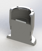
Siemens star lives in a ring (yellow) with a threaded retaining ring to hold it down (blue). There are three set screws which can push it around while keeping it up against a face inside the outer part (red). The outer part can be screwed in and out on the green piece to get the target in the right place WRT the objective.

1731815965657.png


Rest of the design is coming along. There's a lot of parts. It's not going to be cheap to have these all made in only a quantity of 50 or so.
 

OAPOli

Member
Joined
Sep 26, 2022
Messages
623
Location
Toronto
Format
Medium Format
The target is demagnified onto the film plane by the ratio of the focal lengths of the lens under test to the collimating lens. That is if there is a 24mm diameter target, a 50mm lens under test, and a 250mm collimating lens, the image of the target on the film plane will be diameter = 24 * 50/250 = 4.8 mm. There's probably some good reason to keep this from getting too small, and certainly to keep it from getting too large - if the demagnification was 1 you'd start to get close to overfilling the film gate.

Any focal length lens would be able to simulate infinity (produce a collimated beam), but because the collimator is a simple lens, one wants it to be fairly slow to keep its own aberrations from mattering. For ex if the collimator were a focal length 250mm lens of about 40mm diameter (basically a +4 closeup lens), its own focal ratio is 250/40 = 6.25. And the edge of the 24mm target is 12mm off-axis from the collimating lens 250mm away, so it's nearly on axis, which means that the curvature of field or other aberrations of the collimating lens will be small. OTOH, if the collimating lens is very long focal length, the device gets uncomfortably large.

That makes sense, thanks. Another argument for a longer focal length is that is it less sensitive to a calibration error, and easier to calibrate due to high magnification. A small deviation from true infinity will still yield reasonably collimated rays whereas a shorter lens has a shorter range.
 

ic-racer

Member
Joined
Feb 25, 2007
Messages
16,483
Location
USA
Format
Multi Format
Just to mention again, what a fantastic project you are very talented!

I suspect you are an Engineer, and I'm just someone that can break things, but this might be a source of failure if the device topples or someone leans on it.

Screen Shot 2024-11-17 at 8.58.45 AM.png
 
OP
OP

Reveni-matt

Member
Joined
Jul 24, 2024
Messages
47
Location
Canada
Format
35mm
Just to mention again, what a fantastic project you are very talented!

I suspect you are an Engineer, and I'm just someone that can break things, but this might be a source of failure if the device topples or someone leans on it.

Thank you. I'm actually not a an engineer, but I do have a diploma in electronics engineering. The mechanical is all self-taught.

The wall thickness in the area you highlighted is 1.5mm, at a 25mm diameter, I think this should be thick enough to resist any reasonable force.
 
OP
OP

Reveni-matt

Member
Joined
Jul 24, 2024
Messages
47
Location
Canada
Format
35mm
I sent in my 15 parts and drawings to a machine shop in China that I used with the Camera Tester. I asked for pricing for samples and at a quantity of 50 sets. Hopefully they come back with positive news.
 
OP
OP

Reveni-matt

Member
Joined
Jul 24, 2024
Messages
47
Location
Canada
Format
35mm
Prices came back, at a quantity of 50 they are not too far out of my target costs. Single samples of each (there are 15 pieces) will total $1000 USD though.

It was all quoted out in 6061-T6 aluminum, but I am worried about wear in the objective focusing thread. Most of the threads will only be used sparingly and applying a little anti-seize should prevent any practical issues there. The use of a thicker paste or wax would help the eyepiece and target focusing mechanisms stay put.

The objective focusing mechanism could be manipulated tens of thousands of times in it's lifespan, so I'm worried about the wear that would cause long-term, even with regular cleaning and lubrication.

I'm considering ordering it anyway and building a simple motorized test jig to turn the barrel back and forth many times and see how much wear/slop is induced.
 

ic-racer

Member
Joined
Feb 25, 2007
Messages
16,483
Location
USA
Format
Multi Format
The comment in #33 above was assuming the device was 3d printed in some polymer. Will this be metal?
 
OP
OP

Reveni-matt

Member
Joined
Jul 24, 2024
Messages
47
Location
Canada
Format
35mm
The comment in #33 above was assuming the device was 3d printed in some polymer. Will this be metal?

That's the goal. I need to consider some ways to simplify it, though. There are too many parts, and I'm worried about how to get the focus adjustments:

1. Eyepiece mount
2. Siemens star mount
3. Objective mount

To be stiff and hold their set position well as well as survive a lifetime of wear in the case of #3.
 

albada

Subscriber
Joined
Apr 10, 2008
Messages
2,175
Location
Escondido, C
Format
35mm RF
You probably already know this, but you should never allow aluminum to rub against aluminum. If you do, sooner or later the two parts will exhibit what is called "galling", and the two threaded parts will seize, even with grease. I had this happen with a cheap no-name zoom lens. For metal, the rule is: aluminum rubs against brass. I suppose aluminum rubbing against plastic would be okay.

Mark
 

ic-racer

Member
Joined
Feb 25, 2007
Messages
16,483
Location
USA
Format
Multi Format
I was actually imagining you collimator done up in resin like this. I had JLC3DP print these in resin and they are absolutly fantastic. But you probably know much more about it than myself. I do have one of your light meters. Those are 3d printed, yes?


DSC_0002.JPG
 
OP
OP

Reveni-matt

Member
Joined
Jul 24, 2024
Messages
47
Location
Canada
Format
35mm
I was actually imagining you collimator done up in resin like this. I had JLC3DP print these in resin and they are absolutly fantastic. But you probably know much more about it than myself. I do have one of your light meters. Those are 3d printed, yes?


View attachment 383967

I want to avoid printed parts where I can because there is still a stigma against them.

However, plastic in a few places here would make my life quite a bit easier.
 

Alex Varas

Subscriber
Joined
Mar 24, 2018
Messages
801
Location
Bilbao
Format
Medium Format
For me the most important when I got my auto-collimator was to put it perfectly perpendicular to the base (Blight auto collimator) and mirror base for 35mm and medium format cameras, I had to do them myself with cut to size mirrors and additional basement.

I will fund your project, Matt! Having a second auto collimator is worthy in my opinion.
 
OP
OP

Reveni-matt

Member
Joined
Jul 24, 2024
Messages
47
Location
Canada
Format
35mm
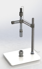
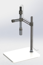
In an effort to reduce the part count, solve the thread concern, and shrink the BOM cost, I redesigned it to make heavy use of MJF 3D prints and put in some carbon fibre tubes. I got the quantity of aluminum parts down to 4 ( one is just a plain tube segment), 5 MJF prints, a bunch of fasteners, and some other stuff. I'm looking at a base 19mm melamine particle board with reinforcement underneath.

The main tube would be black anodized so it's dark inside and allow for laser engraving the focus marks on the barrel.

The threads are an interference fit and the plastic has been segmented so that it will be a snug and wear resistant.

haven't designed the LED and housing yet.


Screenshot 2024-11-22 171129.png


1732314055098.png
 
OP
OP

Reveni-matt

Member
Joined
Jul 24, 2024
Messages
47
Location
Canada
Format
35mm
Feeling good about the design so far.

I also designed a lens test mount with a micrometer mirror. It uses a micro four thirds mount, which would be used with adapters to get the lens setup needed. The adapters would need to be measured and calibrated to compensate for any manufacturing inconsistencies.
 

Attachments

  • pic4.JPG
    pic4.JPG
    187.4 KB · Views: 11
  • pic3.JPG
    pic3.JPG
    171 KB · Views: 10
  • pic1.JPG
    pic1.JPG
    175.5 KB · Views: 10
OP
OP

Reveni-matt

Member
Joined
Jul 24, 2024
Messages
47
Location
Canada
Format
35mm
Things have been moving slowly because of the postal strike here in Canada, which is coming up on a month. Many parts I ordered for this build are trapped in the postal system.

I got new custom made siemens stars today, they are great. This is the centre of the star under 600x magification:

2024-12-12 11.13.33 (Large).jpg


This is the view off a mirror through my proof of concept autocollimator:

2024-12-12 12.14.13 (Large).jpg


Here's the view of the siemens star projected onto some film in a K1000 with 50mm lens wide open. Harder to see and much less crisp than the view just off the mirror with no test lens:

2024-12-12 12.47.54 (Large).jpg


Waiting for more parts to proceed.
 

ic-racer

Member
Joined
Feb 25, 2007
Messages
16,483
Location
USA
Format
Multi Format
You know if you put some indicators of distance from the center, you can use your collimator to quantify lens sharpness at center and edges.

 
OP
OP

Reveni-matt

Member
Joined
Jul 24, 2024
Messages
47
Location
Canada
Format
35mm
You know if you put some indicators of distance from the center, you can use your collimator to quantify lens sharpness at center and edges.


On the siemens star itself or on the eyepiece reticle?
 
Photrio.com contains affiliate links to products. We may receive a commission for purchases made through these links.
To read our full affiliate disclosure statement please click Here.

PHOTRIO PARTNERS EQUALLY FUNDING OUR COMMUNITY:


Ilford ADOX Freestyle Photographic Stearman Press Weldon Color Lab Blue Moon Camera & Machine
Top Bottom