LED based point source enlarger

Forum statistics

Threads
197,385
Messages
2,758,225
Members
99,483
Latest member
bobequus
Recent bookmarks
0

koraks

Moderator
Moderator
Joined
Nov 29, 2018
Messages
20,547
Location
Europe
Format
Multi Format
The cause of what I was seeing is that a COB is not a point source, nor is it a narrow filament. If you look at a COB led, you'll notice that the light emitting surface is usually 1x1cm for a 10W device and it gets larger as power goes up since the individual LEDs that make up the COB are exactly the same and usually placed at the same pitch.
A single element LED you can regard as a point source, but anything that's made up of several elements won't effectively be a point source anymore.

Edit: for clarification, this is the type of COB LED I used for said test. The area covered by the arrays if LEDs is about 20x20mm effectively. No matter how you fiddle with the positioning, there's no way something like this is ever going to act as a point source.
100W%20cob%20led%20RGB.jpg
 
Last edited:

John Tindle

Member
Joined
Jun 15, 2021
Messages
21
Location
France
Format
Digital
Thank
For my own work (which requires color, so also red in addition to green and blue), it's a dead end street since there simply are no single-element LEDs that are powerful enough, so I stick to LED panels, which means a diffuse light source, but I do keep the condensors in my 138 in place, so it's a diffusor/condensor setup effectively.


Koraks, I absolutely agree. I shall not be trying to build a colour head. I am not at all clear how well narrow bandwidth colour leds will interact with the paper. Also there are indeed no single tricolour LED powerful enough (..perhaps).. The only solution would be to do sequential exposures of R,G,B ...... but that is for somebody else to try! Apart from anything else grain structure (well dye cloud structure) is very different in colour and I am not certain that point source will offer significant improvements .... nor indeed with chromogenics like XP2.
As to green powerful enough, I shall try. Bearing in mind that I shall sequentially expose to blue and green for almost all prints, different exposure times for the two will be normal anyway.

And yes a COB array is a no-no as a point source. The one in your photo is a little strange too. My red LED have colourless lenses for the most part. Some have clear red lenses, no problem. But apparently some red LED use a red phosphor which will give major colour "spread". You might want to check (Strangely the easiest way is to look at the forward Voltage specification (2.xV would be true Red LED, 3.xV would be a phosphor LED)
 
Last edited:

John Tindle

Member
Joined
Jun 15, 2021
Messages
21
Location
France
Format
Digital
Collimating means you bend the rays so they become parallel. So here it seems you're basically saying the same thing twice: converge to straight path sounds pretty much the same as collimation to me. Perhaps a drawing would help? Do you mean collimate first, and then converge them into a single node that aligns with the upper condensor?

My understanding is that almost all condensers are double plano convex lenses. The first condenser lens renders the light parallel (ie the source is at the focal length from the first). The second converges the light into a node at the iris of the projection lens
 

John Tindle

Member
Joined
Jun 15, 2021
Messages
21
Location
France
Format
Digital
Likely he just misunderstood the design of a condernser. To reduce abberations (which not only are an issue for imaging, but lighting rays) at the classic condenser a single element convex lens was substituted by two plano-convex lens element with inbetween them paralled rays. Thus this paralel part is not a necessity for illuminating the fil image, but to optomise the the condenser as such.

AgX, I should have read the whole thread before making my last comment. I 100% agree with you
 

John Tindle

Member
Joined
Jun 15, 2021
Messages
21
Location
France
Format
Digital
That is another experiment I will have to try. I still have an old RGB LED strip lying around where the back is already separating from the clear flexible plastic cover after about 5 years. Definitely not quality material, but should work:whistling:

Distributed
Doubtless workable for a diffuse source. Just one caveat. I used a royal blue led because its light largely falls outside the sensitivity curve for the green emulsion(s) of Ilfords multigrade. Or so I have read. The blue LEDs in those strips are perhaps slightly lower frequency.... the end resuit would be slightly softer prints as the Blue will activate the green emulsion somewhat. It would be nice to know which papers fall foul of this problem. I am pretty sure that this was discussed in another forum, but have failed to find it.
 
Last edited:

koraks

Moderator
Moderator
Joined
Nov 29, 2018
Messages
20,547
Location
Europe
Format
Multi Format
as a point source. The one in your photo is a little strange too.
All red power leds I have come across are red in color. It's not the color of the lens, it's the surface of the led die itself. A phosphor? Don't think so. It would be inefficient, have an unnecessary short lifetime and materials with a suitable bandgap are amply available.
 

John Tindle

Member
Joined
Jun 15, 2021
Messages
21
Location
France
Format
Digital
All red power leds I have come across are red in color. It's not the color of the lens, it's the surface of the led die itself. A phosphor? Don't think so. It would be inefficient, have an unnecessary short lifetime and materials with a suitable bandgap are amply available.

Koraks,

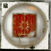
I agree! plenty of semiconductors with the right bandgap, phosphors add to the price, reduce efficiency etc. And yes the die itself looks red.
Notwithstanding I had heard talk of phosphor based reds ..... the existing 633nM are regarded by some as not particularly visible and phosphors give a "more friendly" light. You also only need one fabrication facility for doping the semiconductor material and then coat with a variety of phosphors. So this maybe something that marketeers have dreamt up. And all this as a spin off from warm white LED research eg Mg2Al4Si5O18:Eu2+
Equally the person who told me this might be talking BS ..... note the Eu at the end, seriously expensive unless you happen to "own" Inner Mongolia.

You clearly know what you are talking about, so happy to accept that the COB is equipped with "proper" red LED! (If indeed phosphor based LEDs exist)
 
Last edited:

John Tindle

Member
Joined
Jun 15, 2021
Messages
21
Location
France
Format
Digital
Hello John,
You need the correct condensers for the magnification you are enlarging, and for the lens you are using. To give an idea of this, you can look at the Durst 138 manual pages 30 and 31. You see the different combinations of condensers used for different scenarios.

Marco,
Once again thanks for the information and guidance. I have had a chance to look through the document you mentioned and a very similar one found elsewhere on the internet. I have never seen a Durst 138 except in pictures, but from what I have read this is a huge beast. People talk of being unable to lift a crate carrying the full set of condensers!!!

But that lack of a feeling for scale leads to some difficulty in interpreting those lens/condenser tables. My working hypothesis (which has very little supporting evidence) is that

1) the numbers associated with the condensers (eg 240) refer to the focal length of the element (sadly it could also be the diameter)
2) and that consequently the distance from lightsource to condenser is around 240mm (through a 45 degree mirror?)

If that is correct, then my tentative suggestion is that the first condenser lens is intended to collimate the light (to parallel) and the second to direct it at the projection lens. For short focal length projection lenses this would appear not to be possible (presumably because fabricating a large condenser lens with short focal length is difficult and may not physically fit into the available draw space because of its highly curved form) So for objectives below 100mm the first condenser actually renders the beam convergent (ie bends beyond parallel) and the second condenser finishes the job.

So a couple of questions if I may
  1. From your experience, how reasonable is my "theory"
  2. I note that there are 240, 240R, 240PT,240T and 240H lenses ...... I do not even have a reasonable guess as to what the differences might be. Do you have any ideas please?
 

koraks

Moderator
Moderator
Joined
Nov 29, 2018
Messages
20,547
Location
Europe
Format
Multi Format
You clearly know what you are talking about, so happy to accept that the COB is equipped with "proper" red LED!
Well, truth be told, it's hard to be sure. I do have to say though that I stick to 660nm for red since I have the impression that the 620-630nm ones have a more pronounced secondary emission in the green part of the spectrum which is not nice when doing color! However, the led dies look pretty much the same between the 620 and 660 ones. You do notice that 660 is a bit deeper and consequently dimmer (due to the sensitivity of the human eye) than 620, which is probably why 95% of the red leds are 620 instead of 660.
 

Sean

Admin
Admin
Joined
Aug 29, 2002
Messages
13,040
Location
New Zealand
Format
Multi Format

MattKing

Moderator
Moderator
Joined
Apr 24, 2005
Messages
51,868
Location
Delta, BC Canada
Format
Medium Format
Thankyou Sean!
 

distributed

Member
Joined
Sep 11, 2020
Messages
127
Location
Switzerland
Format
Multi Format
Doubtless workable for a diffuse source. Just one caveat. I used a royal blue led because its light largely falls outside the sensitivity curve for the green emulsion(s) of Ilfords multigrade. Or so I have read.

I have read the same thing, both on this forum and elsewhere on the internet.

FWIW with my 3x3 RGB COB LED I reach an ISO(R) of slightly less than 60. Depending a bit on measurement I have seen values in the range 53-57. At this point small differences quickly show, that's why I feel more comfortable saying "slightly less than 60". Ilford publishes a minimum range of 50 for MGRC grade 5.
 

John Tindle

Member
Joined
Jun 15, 2021
Messages
21
Location
France
Format
Digital
All red power leds I have come across are red in color. It's not the color of the lens, it's the surface of the led die itself. A phosphor? Don't think so. It would be inefficient, have an unnecessary short lifetime and materials with a suitable bandgap are amply available.

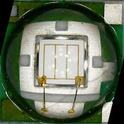
Koraks, your expertise please. Until now I have been using a royal blue bead for my experiments. I wanted to try the green bead, largely because it is easier to see! To my surprise the image on the baseboard was made up of a number of spots. So I used my noddy USB microscope to take photographs of all my candidate LED. So here is the blue, a single large die

blue.jpg

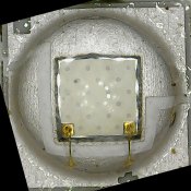
And the green that I was using. It is very clear that there are a number of point sources, embedded I think in a green phosphor

green.jpg

If this is the case the green will almost certainly be contaminated with blue and or UV, a nightmare with multigrade paper

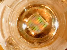
So I looked around in my toy box. Here a different 3W green bead
green bead 2.jpg
And a third type of green bead
green bead1.jpg

Just for reference the red
red.jpg

Would you agree with my assessment on the first of the green LED?

For everybody thinking of building a mutigrade LED head (if I am correct), be very careful of which green LED you use. Mine is supposed to be a CREE

I also suspect that, for my point source experiments, a phosphor based LED will have a very different beam form (since the phosphor will radiate in all directions)
 
Last edited:

koraks

Moderator
Moderator
Joined
Nov 29, 2018
Messages
20,547
Location
Europe
Format
Multi Format
Would you agree with my assessment on the first of the green LED?
I'm not sure, but I do know that the beads I use are all of the 2nd or 3rd type in your photos, and that they seem to work fine. I have no experience with the first type with the dotted die. It does seem to be of a different type for sure, but haven't come across that type myself.

Did you do the cd/DVD test to get a qualitative impression of the spectrum?
 

John Tindle

Member
Joined
Jun 15, 2021
Messages
21
Location
France
Format
Digital
Did you do the cd/DVD test to get a qualitative impression of the spectrum?
Koraks
Have not done the DVD test, I am trying to build a small spectrometer based on web cam and diffraction grating. However that is taking a back seat to this project.

It looks as though the green led in question may indeed be a Cree device, or at least a copy. A photo of a real Cree device
Creegreen.png
A pretty poor image, but the same type of pattern. The diodes are Silicon Carbide 5

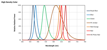
The spectral response for this Cree range is.
creespectralresponse.png
It could be a fault of the artist, but both the green and amber leds spectra show a slight blip at a typical SiC wavelength.

It corresponds more closely to a phosphor than a true green. note the shift towards the blue


greenspectral.png

So it is my belief that the green in question is a phosphor based one. So unproven, but highly suggestive.
I will look properly when the enlarger and spectrometer are both built, but for now I will stick to the greens shown in later photos
 
Last edited:

koraks

Moderator
Moderator
Joined
Nov 29, 2018
Messages
20,547
Location
Europe
Format
Multi Format
It corresponds more closely to a phosphor than a true green.
I'm not so sure about that; I would have expected the peak to be far wider and deviating more from a bell curve shape. Small blips on the sides of the central peak are usually the effects of contaminants in the chemistry used in manufacturing. I have the strong impression they're often excluded from these plots...

Your spectrometer sounds like a fun/useful gizmo; be sure to post about it when you get round to it!
 

John Tindle

Member
Joined
Jun 15, 2021
Messages
21
Location
France
Format
Digital
Your spectrometer sounds like a fun/useful gizmo
Koraks,

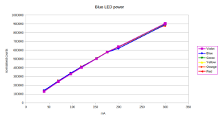
No, the proper spectrometer is sadly not built, but I suddenly remembered that I characterised the LEDs I intended to use some time ago. I used an AS7263 six band sensor, which is a MEMs device with diffraction grating. Not a proper spectrometer, but not too bad. My objective was to measure output against current. I have normalised the 6 measurement channels to highlight relative output power. The royal blue led

blueled.png

I am very happy with that curve. Constant relative output across the 6 channels. With a slight loss of efficiency at higher power. It is the same story with the red LED.

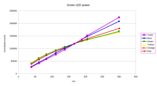
But look at the equivalent graph for the green LED

greenled.png
The green/yellow channels show a rapid fall off in efficiency, while the blue/violet grow almost linearly. By 300mA (circa 1W) the blue output exceeds the green output (in absolute count)

So I am now convinced that the device is a phosphor based green whose effect on multigrade paper will vary with current. At high currents, soft grades will be more and more difficult to achieve.
....... Of almost no importance to anyone not building a LED based multigrade head!
 

AgX

Member
Joined
Apr 5, 2007
Messages
29,990
Location
Germany
Format
Multi Format
Thus be on the save side on evenness, one would have to build a micro- mixing chamber (like jus layers of diffusors) which exit window would be the effectice point sporce then?
 

koraks

Moderator
Moderator
Joined
Nov 29, 2018
Messages
20,547
Location
Europe
Format
Multi Format
@John Tindle that is very interesting indeed! A few months ago I did a similar measurement, but with PWM modulation. I noticed no distinct non-linearities that way, but the green leds I used were not of your dotted suspected-phosphor type. Still, I'd stick with PWM if only for the simplicity of the driver, at least if you want accurate control over light output. It's just so much easier than linear dimming.
 

John Tindle

Member
Joined
Jun 15, 2021
Messages
21
Location
France
Format
Digital
@John Tindle that is very interesting indeed! A few months ago I did a similar measurement, but with PWM modulation. I noticed no distinct non-linearities that way, but the green leds I used were not of your dotted suspected-phosphor type. Still, I'd stick with PWM if only for the simplicity of the driver, at least if you want accurate control over light output. It's just so much easier than linear dimming.
Mmmm, two schools of thought there.

If you want to drive from an arduino/ESP etc microcontroller and you have a well behaved voltage source, then you are right. PCM=Simplicity itself ...
but I have some very nice constant current modules that take pcm in and translates that into constant current. As SMPS, the modules take in "any old" voltage (above that of the LED obviously).

Both are PCM solutions, so same software solution. Just different approaches to PSU

And you raise an interesting question about PCM and phosphor LEDs:- If the saturation time of the phosphor is shorter than the PCM period, little or no problem. As the duty cycle nears 100% (and if the phosphor becomes saturated) then you would expect to see colour shift; And with low duty cycle PCM I suspect that you would see better linearity (assuming that there is good heatsinking to keep the junction temperature down)

Thank you for the stimulating debate, it has helped greatly in clearing my thinking
 

John Tindle

Member
Joined
Jun 15, 2021
Messages
21
Location
France
Format
Digital
one would have to build a micro- mixing chambe
Hi AgX

Interesting idea. I too had thought of a mini diffuser to get the source up to a reasonable size. I have been revisiting my old optics knowledge, heavily augmented by the documents passed on by Marco. It looks possible that I will need to do that, because (in the paper by
Jens Jørgen Jensen) it is stated that the image of the source should fall at the nodal point of the final lens and be the size of the aperture. With single die LED this is pretty much impossible! That is a magnification of almost 10. So over half a metre away from the condenser(f=85mm)

However there will be a loss of coherence (and hence light), so I shall try and avoid that in the first instance. But it may be necessary. I will keep you posted.

First some experiments to see what I can get away with!

I have perhaps not been clear about the green LED. It is just one LED, so no mixing needed or possible. If I have misunderstood your point, please let me know
 

koraks

Moderator
Moderator
Joined
Nov 29, 2018
Messages
20,547
Location
Europe
Format
Multi Format
but I have some very nice constant current modules that take pcm in and translates that into constant current
Yeah, I use MP24894 which does the same, and can dim linear or pwm depending on how you drive the dim pin. But pwm is more flexible (it also goes down to very low duty cycles where linear dimming is unavailable) and likely more accurate / less prone to minor fluctuations in voltage. Unless the choppy nature of pwm is a problem (which it isn't when enlarging), I consider pwm preferable.
 

John Tindle

Member
Joined
Jun 15, 2021
Messages
21
Location
France
Format
Digital
It has been a long time since the last post, I have been waiting for some components (and I am still waiting for others).
From previous conversations in this thread, I learned that point source enlargers have commonly a third objective, which lies between the source and the main condensers. And that for optimal performance the source to condenser distance needs to be varied with magnification.

I undertook a little bit of modelling/calculation based upon the basic optics of my host Durst 805. The standard condenser ( a Bimacon 80) is a pair of planoconvex lenses each with a focal length of 170mm. Calculations indicated that adding a third lens of 170mm might give me the results I needed (this seems to be fairly standard in Dursts when you want to adapt the enlarger for small format work)

But my grasp of theory is often wanting, so I waited to try the idea out in practice... and it seems to work. Here is the revised optical path
upload_2021-8-1_23-26-28.png


So source to upper surface (=left) in this example is around 85mm and the image distance (of the source) is 90mm to the right. Why these figures? Well this setup throws the source image into the nodal point of an 80mm Rodenstock when it is setup for a 5 times magnification of a 645 negative (not shown but just to the right of the righthand part of the condenser array).

some general observations:-
Uniformity of illumination looks extremely good, but has yet to be measured
Alignment of the source is critical, but fortunately is easily done. Stop down the lens and only when the (axial) alignment is perfect does any light pass through the diaphragm. Do not forget to open to maximum aperture afterwards.
Calculations indicate that the source needs to be able to move back and forward around 30mm for a full range of magnifications . I am still waiting for a stepper motor platform to arrive from China


More information when I have built the source trolley
 
Joined
Nov 20, 2020
Messages
90
Location
Western Massachusetts
Format
8x10 Format
I've been thinking about how one might utilize three LEDs to create an RGB condenser enlarger without needing all colors on the same LED unit. While eating dinner tonight, I had an idea that perhaps beam splitters, used in reverse to combine LED channels, could be utilized like in the attached image to make it as though all three LEDs are in the same position. Might that work? I'm no expert on this sort of thing, so there very well be many reasons not to do this.
Beam Splitter for condenser head.PNG
 

koraks

Moderator
Moderator
Joined
Nov 29, 2018
Messages
20,547
Location
Europe
Format
Multi Format
Yes, but there will be a loss of light and thus efficiency.

My main concern is still that it'll be hard to find a small quasi point source LED of sufficient power for each color. If you set something like 25W as a design goal for each channel (which is on the whiny side IMO), you end up with COB LEDs which have a sizeable surface already. Will that still work for a condensor? And can we get COBs at the correct wavelength, yet? For red and green, probably, but for blue as well?
 
Photrio.com contains affiliate links to products. We may receive a commission for purchases made through these links.
To read our full affiliate disclosure statement please click Here.

PHOTRIO PARTNERS EQUALLY FUNDING OUR COMMUNITY:


Ilford ADOX Freestyle Photographic Stearman Press Weldon Color Lab Blue Moon Camera & Machine
Top Bottom