Build a shutter tester for Focal Plane shutters - Cheap, Easy & it Works

Hot Rod

A
Hot Rod

  • 1
  • 0
  • 22
Relics

A
Relics

  • 0
  • 0
  • 28
The Long Walk

A
The Long Walk

  • 1
  • 0
  • 49
totocalcio

A
totocalcio

  • 4
  • 2
  • 85
Untitled

A
Untitled

  • 7
  • 3
  • 154

Forum statistics

Threads
197,449
Messages
2,759,153
Members
99,501
Latest member
Opa65
Recent bookmarks
0
OP
OP

Niglyn

Member
Joined
Feb 26, 2022
Messages
403
Location
Surrey, UK
Format
Analog
Thank you for the in depth explanation once again!

What I'm really interested to know is if Laser 1 în the printed results in fact gives the results for the opening curtain. Meaning am I correct to adjust first curtain based on Laser 1 values or am I having it all wrong?

My lack of understanding derives from the fact that both lasers must be involved for the assessment of each / any curtain.

Laser 1 can only show the exposure it sees on the right side of the film gate.
Laser 2 can only show the exposure it sees on the left side of the film gate.

Neither Laser 1 or two can measure the travel time of the curtains.
It is the maths used from both laser 1 and 2 times which gives the curtain travel time.


The travel time of the first curtain has to be displayed somewhere, so it is put on the right.
The travel time of the second curtain then goes on the left.


Many service manuals give the travel time of the curtains in mS, normally based on a sensor spacing of 32 or 20mm.
(Olympus OM-1 states 12mS, for example)
As the first & second curtains are indexed (second starting to close when first is open or 50% or 25% or 12.5% etc)
if the curtain travel times are correct, the shutter speed must be correct.

The cameras I generally muck about with do not have such detailed service manuals, so it is a case of balancing the curtains,
seeing what the exposure is & increasing or decreasing curtain speed.

Important to understand:-
Curtain travel time is the time it takes for the curtain to travel between the two lasers, it is not how fast the the curtain is travelling.
'Shutter speed' is a misnomer. The shutter is always the same speed. It is the delay of the second curtain closing which changes the exposure.

So, based on the OM-1,
If curtain 1 says 10mS, it has covered the 32mm distance too fast and has to be slowed to 12mS.
If curtain 2 says 21mS, it has covered the 32mm distance too slowly and needs speeding up to 12mS
 

alinCiortea

Member
Joined
Jan 1, 2008
Messages
74
Location
Romania
Format
Multi Format
Thanks!

That's what I needed to know. Since I don't care about the math from a practical standpoint, knowing that the values on the left column refer to second curtain and values on the right column refer to the first curtain is all that matters.

For the time being I'm working on soviet rangefinders and some Japanese Leica clones (Nicca and Leotax). Since they are more or less copies of the Leica II/III, I guess I could use the Leica specs. The main issue with the soviet ones is their quality control and design alterations. I also read a forum thread about the physics behind this shutter design and it's a lot more complicated than I thought. The two curtains are not directly linked at a first glance, but in fact they somewhat are through induced friction. The second curtain drum spins 'freely' on the first curtain shaft but since one rides on top of the other, when the shaft spins it will also induce a spinning motion to the drum, literally dragging it along (except for 1/30 or 1/25 when the first curtain is at a full stop before the second starts its motion). Similarly, when the second curtain starts moving, the rotation of the drum will 'push' the shaft of the first curtain, increasing it's speed. On the other hand, the ribbons of the second curtain must travel between the small rollers on the ends first curtain roller shaft and the metal edge / ribbons of the first curtain, thus loosing some of its momentum. These induced frictions mean that almost always changing the tension on one curtain translates into slight changes in the recorded times of the other curtain and that's one thing that was puzzling me before but now it makes sense (from what I've seen, mostly the increase in tension for the first curtain will also decrease CTT for the second curtain). This is probably one of the main reasons this types of shutters are so difficult to get right (or maybe it's just me being a complete idiot).
 

alinCiortea

Member
Joined
Jan 1, 2008
Messages
74
Location
Romania
Format
Multi Format
It's me again, the devil's advocate :smile:)

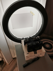
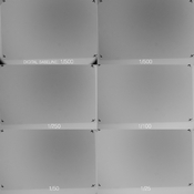
I decided to do another test after some more fiddling with the tensions, so I checked the speeds with my Fujifilm XE3 (I've attached a photo of the setup).
Methodology:
film camera set to B, kept in open state.
digital camera set to ISO3200, f16, 1/500 (looking back I should have the widest aperture possible to blur the background as I think it's easier to spot gradient fading). The exposure was made in such a way as to have everything in the middle of the histogram (so 0EV compensation)
picture taken through the open film gate for reference.
digital set to 1s, film camera set to 1/500, release digital -> release film camera
decrease ISO by one stop, decrese SS on film camera to 1/250 and so on

The only editing in post is the desaturation for easier analysis. At the end of the day all looks decently good. Still have a hard time interpreting some of the results of the tester. These are for the 1/100 speed as it's probably the one I use most and seems the closest to the baseline image.

AVERAGES LASER2 LASER1
shutter Speed Av mS 10 9 18
Curtain Travel Av mS 10 20 28

Shutter Speed Av Vul 10 1/112 1/57

I also did another thing... I covered receiver 2 and used only pair number one to asses shutter speed (not travel time) at different points of the film gate. As expected there's a gradient from right to left (slowest at the right of the film gate, fastest at the left). Further adjustments didn't improve things more than marginally. It's probably the time needed for the drum to beat inertia and get up to speed.

IMG_20230528_225531.jpg test2_small.jpg
 
OP
OP

Niglyn

Member
Joined
Feb 26, 2022
Messages
403
Location
Surrey, UK
Format
Analog
AVERAGES LASER2 LASER1
shutter Speed Av mS 10 9 18
Curtain Travel Av mS 10 20 28

Shutter Speed Av Vul 10 1/112 1/57


Hi,
Could you post the whole screenshot, so we can see all the figures.

I'm not developing the Arduino Nano version anymore, mainly because I don't have it. Replaced with the ESP32.
I think on the ESP32 I will change the words 'Shutter Speed' to 'Exposure'. This may make things easier to understand.

I have had a look at the Fed2 shutter mech. It is almost identical to the ones I am quite familiar with.

I do not understand 'inertia' or 'friction' between the middle and outer parts of the drum as you have explained it.
The inner drum should move freely and independently from the outer part. There should be no friction or interaction between the two parts.
The ribbons for the first curtain attach to top & bottom and the second curtain attach to the centre of the drum.

On the other side of the camera are two rollers with internal springs. One has the first curtain glued to it, the other has second curtain ribbons.
It is the spring tension applied to these rollers that pull the curtains & ribbons, there should be no friction or first curtain pulling the second along.

Whilst the inner and outer of the drum move totally independently, there are two crucial things. The two parts of the rollers are indexed by the little notch on the top, which holds the two parts in alignment. This is disengaged by the second curtain shutter button, so the second curtain starts to move when the first curtain has travelled the correct distance (full, 1/2, 1/4 1/8 etc) This notch, which is on the inner drum, must align in exactly the correct position to stop the outer rotating and must be aligned correctly in the camera body, so the second shutter release, engages with it correctly,

The second crucial part, is the position of the above described indexing in relation to the length of the first curtain ribbons and second curtain.
These must be precisely glued to the drum to give the correct length, else they will either not slightly overlap at end of travel, leave a gap when winding on (fogging the film), over or under travel.

I have never found anywhere that explains or details how to align all of these up.
In the video below, it can be seen that the curtains are replaced, but nowhere in this video does it show or explain how to correctly replace and align the shutter cloth.

My solution was to make a jig. Using a shutter mech that had not been previously disassembled, I made a clamp to hold the drum, with a tab that ensures the outer and centre are held in the correct indexed position. This is mounted on a board, marked with exactly where the edge of the two curtains should be, at un-cocked position, with clamps to hold the metal edges in position. It is then an easy matter to glue the ribbons & curtain onto the drum with rubber solution, knowing that it is all perfectly aligned.


below i a link to a video showing a Fed shutter curtain replacement, however nothing is shown of how to correctly assemble and align it.

 
OP
OP

Niglyn

Member
Joined
Feb 26, 2022
Messages
403
Location
Surrey, UK
Format
Analog
Here is a snippet from a service manual, for a camera with similar shutter


Capture.JPG


This is my jig. Due to no longer having a proper metalworking workshop,
I had to use what I had. Not pretty, but it works,

Two parts of drum are locked together, using the indexing notch on the top of
the centre drum, in the same position they would be in the camera, in the
un-cocked position.

The metal edge of the curtain is then clamped in place, so nothing moves.
The ribbons can now be re-glued onto the drum, knowing everything is in
perfect alignment.

The shutter is upside down, so if you look carefully at the bottom of the drum,
where the ribbon has already been stuck, you will see a double pencil mark
and the indexing pin, holding the two parts of the drum in alignment.


20220430_113813 (003).jpg
 
OP
OP

Niglyn

Member
Joined
Feb 26, 2022
Messages
403
Location
Surrey, UK
Format
Analog
Here is the current version of the Arduino Nano code. Please ensure you update to this one.
Between V2.9 and 3, I changed it to show curtain 2 on the left and curtain 1 on the right, but
a slight error crept in on the LCD.

Moving forward, I will be using the ESP32, as detailed somewhere in this thread & would suggest if building from new,
you consider using the ESP32 board instead.

The ESP code will be issued to those wanting it, as a bin file. This will save having to muck about with adding libraries & just gets
squirted onto the board using the Exprisiff flash loading tool.
 

Attachments

  • shuttertimer_2_lasers_3_0_3.txt
    22.8 KB · Views: 99

ic-racer

Member
Joined
Feb 25, 2007
Messages
16,483
Location
USA
Format
Multi Format
I have some cameras where the curtains continue to speed up as they travel across. Depending on camera design, sometimes there may be no way for them to accelerate to terminal velocity before the edge of the curtain reaches the start of the film gate opening. In those cases, the curtains would need to open up a bit as they travel across to keep exposure on the right and left the same.

This video was linked on Sover Wong's site. I don't repair F2 so anyone can correct me if I'm wrong, but I believe this shows the curtains speeding up as they move across and curtain tensions are set so the gap increase. Thus providing equal exposre on both sides of the frame.

Anyway, I have not been following the latest implentation of Niglyn's program, but the one I'm using now calculates the exposure on the first and second half of the frame. I'm not sure if this is in Niglyn's latest, but it would help in set the curtains in these situations. The screen reads, A= exposure deviation in first part of the frame, B = exposure time of middle sensor, C= exposure deviation at second part of frame, S= "one-over" version of "B", Er= deviation of middle sensor from closest nominal speed (1/125 in this case).


screen-7.jpg
 
Last edited:
OP
OP

Niglyn

Member
Joined
Feb 26, 2022
Messages
403
Location
Surrey, UK
Format
Analog
I have some cameras where the curtains continue to speed up as they travel across. Depending on camera design, sometimes there may be no way for them to accelerate to terminal velocity before the edge of the curtain reaches the start of the film gate opening. In those cases, the curtains would need to open up a bit as they travel across to keep exposure on the right and left the same.

This video was linked on Sover Wong's site. I don't repair F2 so anyone can correct me if I'm wrong, but I believe this shows the curtains speeding up as they move across and curtain tensions are set so the gap increase. Thus providing equal exposre on both sides of the frame.


Great slo-mo. There are quite a few around, showing different shutter types.

Old grease would slow the acceleration of the curtains and starting from zero, they will take a bit of time to get up to speed.
These are old cameras, with old designs, so trying to get them spot on is never going to happen.

Assuming the mech has been degreased and running smoothly, it is a juggling act with the spring tensions to get the curtains balanced
and the same exposure on either side of the frame.

Alin is having problems, with his readings showing double the exposure value at one end of the frame, compared to the other.
 

alinCiortea

Member
Joined
Jan 1, 2008
Messages
74
Location
Romania
Format
Multi Format
I'm already running v3.0 of the script.
I've attached two txt files, first is a series of 10 exposures (all at 1/100), the second is the exposure for the right side of the film gate (first result) and the left side (second result), obtained while covering LASER2.

I'm not contradicting the results because I know physics and math don't lie. It's obvious the shutter accelerates overall and I simply couldn't get better results through adjusting tension of the curtains OR different curtain placement (they were initially placed exactly at the points where the originals were)

The thing with friction... yes, the move independently for a certain arc of a circle but the second curtain drum rotates against the main shaft (with the first curtain rollers). There IS friction between the two, even if minute, because when the curtains are under tension the drum has the tendency to be pulled to the left. So whenever one is stationary and the other rotates, the rotating one will rub against the non-rotating one. When both are rotating, one's momentum can add to the other's. It might not matter but these influences exist.
I've polished to a mirror finish all parts that rotate against another part (including retaining screws' shafts, insides of various bushings and so on). I could blame the discrepancies on the old and tired springs or simply the overall shutter design, because I'm pretty confident that no FED has ever left the factory so polished and so well lubricated.

I'll film test it as soon as I have the chance and I'll try to shoot it against an uniform sky to see if there's any light falloff as the shutter travels from right to left.
 

Attachments

  • fed2 laser shutter test 1.txt
    9.1 KB · Views: 82
  • fed2 laser shutter test 2.txt
    1.4 KB · Views: 76

canaq

Member
Joined
Feb 3, 2023
Messages
33
Location
Netherlands
Format
35mm
I finally have found some time to build this tester. But, since all this is completely new to me (Arduino, code), I can't figure it all out, excuse me for this silly question. I have connected everything, uploaded the latest code to my Arduino Nano, checked the port of my LCD (0x27), but my LCD is totally blank (it lights up, but no text). What did I do wrong?
 

snusmumriken

Subscriber
Joined
Jul 22, 2021
Messages
2,348
Location
Salisbury, UK
Format
35mm
I finally have found some time to build this tester. But, since all this is completely new to me (Arduino, code), I can't figure it all out, excuse me for this silly question. I have connected everything, uploaded the latest code to my Arduino Nano, checked the port of my LCD (0x27), but my LCD is totally blank (it lights up, but no text). What did I do wrong?
Are you getting any output to the Serial Monitor (button at the top right of the Arduino IDE)?
 
OP
OP

Niglyn

Member
Joined
Feb 26, 2022
Messages
403
Location
Surrey, UK
Format
Analog
Are you getting any output to the Serial Monitor (button at the top right of the Arduino IDE)?

Hi,
Don't worry about asking questions, many builders maybe new to arduino and have similar issues.
First, a possible quick fix. On tbe back of the lcd, there is a contrast pot. Try turning this.

Did tbe code load OK to the ardino?
If in any doubt, load tbe blink sketch, found in examples.

are you using serial monitor? This is tbe output to the PC screen. What does this show?
 

canaq

Member
Joined
Feb 3, 2023
Messages
33
Location
Netherlands
Format
35mm
Hi,
Don't worry about asking questions, many builders maybe new to arduino and have similar issues.
First, a possible quick fix. On tbe back of the lcd, there is a contrast pot. Try turning this.

Did tbe code load OK to the ardino?
If in any doubt, load tbe blink sketch, found in examples.

are you using serial monitor? This is tbe output to the PC screen. What does this show?

The code did load OK, I got no errors. I will try to adjust the contrast pot, hopefully that will be the easy fix :wink:

I was searching for the serial monitor on my PC, I guess I did find it, but it was empty, so I wondered if I had the right one.
Hopefully I will have some time soon to test these suggestions, thanks for now and I will keep you updated :smile:
 
OP
OP

Niglyn

Member
Joined
Feb 26, 2022
Messages
403
Location
Surrey, UK
Format
Analog
The code did load OK, I got no errors. I will try to adjust the contrast pot, hopefully that will be the easy fix :wink:

I was searching for the serial monitor on my PC, I guess I did find it, but it was empty, so I wondered if I had the right one.
Hopefully I will have some time soon to test these suggestions, thanks for now and I will keep you updated :smile:

Hi,
The Serial Monitor is within the Arduino IDE, the program that you use to load the code. Go to the top menu, select 'tools' and 'serial monitor'
If you are using Arduino IDE 2.0, it appears at the bottom of the screen, you have to drag the horizontal bar up, to make the window bigger.
Cannot remember what the baud rate is set to. Will either be 9600 or 115200.
 

canaq

Member
Joined
Feb 3, 2023
Messages
33
Location
Netherlands
Format
35mm
Hi,
The Serial Monitor is within the Arduino IDE, the program that you use to load the code. Go to the top menu, select 'tools' and 'serial monitor'
If you are using Arduino IDE 2.0, it appears at the bottom of the screen, you have to drag the horizontal bar up, to make the window bigger.
Cannot remember what the baud rate is set to. Will either be 9600 or 115200.

I finally got it to work! First of all I had to adjust the contrast pot (thanks for the tip!), when I did that I noticed the screen only showed blocks. After 5 minutes of searching the web I found out my wiring was wrong (switched A4 and A5), so now it works!

Now it's time to fix everything in place and make sure the lasers are lined up.
 

Tancred

Member
Joined
May 30, 2023
Messages
6
Location
UK
Format
35mm
Hi, I've been lurking here for a couple of weeks or so and now have all the parts (except LCD, which should arrive tomorrow or Saturday) to build an ESP32 variant of this tester. I am a bit of a noob, (hardware wise at least) and so I have a silly question ...... probably the first of several over the coming days!.

Can I just install version 3.0.2 of the Arduino software on the ESP32 as is? Or do i need to use the specific ESP32 version? At a minimum I suspect pin numbering is different for the arduino vs ESP32, so probably need an ESP32 version?

If so is the only way to get this is as a BIN file (great) which will somehow be made available to me if a I request it in a post containing a photo of my finished tester. Have I understood that correctly.

Thanks for any helpful comments
 

Xylo

Member
Joined
Dec 6, 2008
Messages
405
Location
South of Montreal, Canada
Format
Multi Format
Usually BIN files are device dependent. I suspect that you are more likely to get an Arduino sketch which you compile for the ESP32. The Arduino IDE is compatible with the ESP32 (I used it to flash a NodeMCU), so it's not a problem.
 

Tancred

Member
Joined
May 30, 2023
Messages
6
Location
UK
Format
35mm
Usually BIN files are device dependent. I suspect that you are more likely to get an Arduino sketch which you compile for the ESP32. The Arduino IDE is compatible with the ESP32 (I used it to flash a NodeMCU), so it's not a problem.

Thanks, I think perhaps I didn't ask my question very well.

Fundamentally what I was trying to ask was, in order to build the shutter tester using an ESP32 can I compile the " coded for arduino" version 3-0-2 (in Arduino IDE) and load to ESP32 or, do I need either

1) a bespoke sketch for the ESP32 (which I then compile and load to ESP32 with the IDE) or
2) a precompiled BIN for the ESP32

If I need a bespoke sketch or the BIN is the only way to get one or the other to post a photo of my soon to be built tester?

Thanks and sorry for not articulating my original question properly
 
OP
OP

Niglyn

Member
Joined
Feb 26, 2022
Messages
403
Location
Surrey, UK
Format
Analog
I finally got it to work! First of all I had to adjust the contrast pot (thanks for the tip!), when I did that I noticed the screen only showed blocks. After 5 minutes of searching the web I found out my wiring was wrong (switched A4 and A5), so now it works!

Now it's time to fix everything in place and make sure the lasers are lined up.

we want photos :surprised:)
 
OP
OP

Niglyn

Member
Joined
Feb 26, 2022
Messages
403
Location
Surrey, UK
Format
Analog
Hi Tancred,

thanks for contributing to the thread. Please ask questions, it will help others.

So, to answer so far,
Yes, I am a bit of a tease and to stop peeps building the testsr, without even putting a post on here, I send the firmware via private message when requested, providing a photo is sent. This is just for my amusement, so I can see peeps creations. Lego is still winning :surprised:)

you cannot use the arduino code on the esp32. Well you could, but it would need to be tweaked and you would not get the benefit of the new features of the esp32 code.

The bin file I send is the fully compiled code. This way you do not need to add libraries to arduino. This was causing some issues as there are similar libraries for the lcd, for examp!e, which are not fully compatible.

To load the bin file to the esp32, another program is used, found on expresif web site. Not sure if I have posted how to do this, if not, I or one other nice peeps on here will help you.

The Aduino ide program is used to display all of the data onto the computer screen using the serial monitor function.
 
OP
OP

Niglyn

Member
Joined
Feb 26, 2022
Messages
403
Location
Surrey, UK
Format
Analog
I should also add that the lcd only shows basic informstion, the pc screen shows far more data, on the esp32 version, a guessing hat is now used to guess what the camera speeds set at and then show the deviation from this value.currently it uses the standard speeds, 1/30, 1,60 etc. However future versions, it will show the a actual correct speed, 1/32, 1/64, 1/128 etc.
 

Tancred

Member
Joined
May 30, 2023
Messages
6
Location
UK
Format
35mm
I should also add that the lcd only shows basic informstion, the pc screen shows far more data, on the esp32 version, a guessing hat is now used to guess what the camera speeds set at and then show the deviation from this value.currently it uses the standard speeds, 1/30, 1,60 etc. However future versions, it will show the a actual correct speed, 1/32, 1/64, 1/128 etc.

Thank you. I appreciate your confirmation of my noob thoughts/interpretation of the earlier posts in this thread... very helpful. Once I have posted a pic and get the code I will (try and) flash it across to the ESP32 cand take it from there. In theory I have worked out how to use the Espressif DL tool which I have already downloaded to my PC. But theory and practise are sometimes very different things in my experience. So I may be back again for help with that.
 
OP
OP

Niglyn

Member
Joined
Feb 26, 2022
Messages
403
Location
Surrey, UK
Format
Analog
Thank you. I appreciate your confirmation of my noob thoughts/interpretation of the earlier posts in this thread... very helpful. Once I have posted a pic and get the code I will (try and) flash it across to the ESP32 cand take it from there. In theory I have worked out how to use the Espressif DL tool which I have already downloaded to my PC. But theory and practise are sometimes very different things in my experience. So I may be back again for help with that.

Hi,

When flashing the nodeMcu-32 board, the little button next to the USB connector on the right needs to be pressed, before starting the download.

It is best to check within Windows Device Manager, that the computer can see the board connected to the USB port & it has the correct driver.

Here is a video, showing the process of loading code to the ESP32.

 
Photrio.com contains affiliate links to products. We may receive a commission for purchases made through these links.
To read our full affiliate disclosure statement please click Here.

PHOTRIO PARTNERS EQUALLY FUNDING OUR COMMUNITY:


Ilford ADOX Freestyle Photographic Stearman Press Weldon Color Lab Blue Moon Camera & Machine
Top Bottom