Build a shutter tester for Focal Plane shutters - Cheap, Easy & it Works

totocalcio

A
totocalcio

  • 3
  • 0
  • 34
Untitled

A
Untitled

  • 5
  • 2
  • 92
Jerome Leaves

H
Jerome Leaves

  • 3
  • 0
  • 67
Jerome

H
Jerome

  • 2
  • 0
  • 69
Sedona Tree

H
Sedona Tree

  • 1
  • 0
  • 71

Recent Classifieds

Forum statistics

Threads
197,438
Messages
2,758,974
Members
99,498
Latest member
spiewak2
Recent bookmarks
1
OP
OP

Niglyn

Member
Joined
Feb 26, 2022
Messages
402
Location
Surrey, UK
Format
Analog
Right now I'm relying on the onboard VR. But I'm still a bit struggling on the best way to connect the battery. I have connected it to the GND and VIN port so to use the onboard VR, but I'm using 3 AA batteries, which results in 3x 1.5V = 4.5V.
From what I understand, the input power on the VIN port should be in the range of 7 to 12 volts. I could switch to a 9V battery, but that has a fairly short lifespan from what I understand?
I also could keep the 3x AA and use a converter to get a steady 5V output (and use the 5V port on the Arduino), but can I power the lasers and receivers directly from the converter (with the little breadboard)?

You can power the lasers and receivers via your breadboard with 5V or 3 X AA, giving 4.5V. Be careful. Do not exceed 5V.
The power supplied to the receivers gets put into the Arduino as a switching signal. Any more than 5V and your Arduino will die.

I think the safest way, would be to use 4 X AA batteries, an in-line diode to drop 0.8V and connect to Lasers, receivers & Arduino 5V pin.
In theory, the diode will stop reverse current flow and allow the unit to power from batteries or USB.

You could try to be clever & add power saving. Connect the laser & rx power, via a mosfet, controlled via an output pin. (google Mosfet as a switch)
After 30s or a minute, or what ever, the Arduino could go into sleep mode. Add a push button to wake it up, ready for the next test.
 

canaq

Member
Joined
Feb 3, 2023
Messages
33
Location
Netherlands
Format
35mm
Thanks again for the quick replies. For now I'm gonna remove the battery and power it with the usb, it's clear to me I need to do some more research before I'm gonna use a battery safely, without damaging my Arduino :smile:
 

ic-racer

Member
Joined
Feb 25, 2007
Messages
16,483
Location
USA
Format
Multi Format
A focal plane shutter of known exposure is easily constructed: a rotating disc of known slit width and known rpm. Arduino code to give the RPM is easy.
Some cloth horizontal shutters expose the entire frame at 1/30 or 1/60, then the closing curtain cam has been designed to half that distance with each shutter speed increase:
1/60
1/120
1/240
1/480
1/960
 
Last edited:

ic-racer

Member
Joined
Feb 25, 2007
Messages
16,483
Location
USA
Format
Multi Format
Hi ic,
have been watching your posts on the professional tester thread. Nice build. Must have taken a lot of dedication to get all the parts built.

Yep nicking the 3d printed receiver box from that thread would work. Would be nice to have a 3d printed box for my lasers as well, a 6mm tube could be incorporated inside, so the laser could just slot in.

It was really technically very simple to make. All the surface components come attached to the boards. A lot of it just plugs together with connectors.

If you have any interest in building one, I can send you a set of PC boards (the minimum order was 5 each) and some other miscellaneous parts that had to be purchased in multiples.
 
OP
OP

Niglyn

Member
Joined
Feb 26, 2022
Messages
402
Location
Surrey, UK
Format
Analog
It was really technically very simple to make. All the surface components come attached to the boards. A lot of it just plugs together with connectors.

If you have any interest in building one, I can send you a set of PC boards (the minimum order was 5 each) and some other miscellaneous parts that had to be purchased in multiples.

Thanks for the offer but I have no facilities at the moment, not even a soldering iron.
It is a shame there is no longer any support for that tester but at least all the plans are still available. If complete kits were available,, I'm sure many more people would make it.

When I finally get a workshop up and running again, I'm planning a five laser version,
so will work with horizontal & vertical shutters, possibly auto-detecting & maybe tft display, but his will start adding additional cost.
I probably won't peruse the light-meter. Although mine all works ok, getting it into a pretty box is always the problem with home-build projects. TTArtisans Mk2 for $70 looks good.
 

Xylo

Member
Joined
Dec 6, 2008
Messages
405
Location
South of Montreal, Canada
Format
Multi Format
I probably won't peruse the light-meter. Although mine all works ok,
And you can always sunny-16 them to check how they behave.

I got the TTartisan meter MK1 last spring and can vouch for it's outstanding build quality.
 

Xylo

Member
Joined
Dec 6, 2008
Messages
405
Location
South of Montreal, Canada
Format
Multi Format
Yes, but the shutter speeds the meter shows will be just ever slightly off as it lists the speeds as 1/60, 1/125, 1/250 and not the usual 1/50, 1/100, 1/200 found on leaf shutters.
But unless you're a picky zone system aficionado (not even the regular zone system aficionados), you won't see any important difference, especially at the higher speeds.
 

Jchick

Member
Joined
Jul 30, 2023
Messages
8
Location
Guyton, GA
Format
35mm
Yes, but the shutter speeds the meter shows will be just ever slightly off as it lists the speeds as 1/60, 1/125, 1/250 and not the usual 1/50, 1/100, 1/200 found on leaf shutters.
But unless you're a picky zone system aficionado (not even the regular zone system aficionados), you won't see any important difference, especially at the higher speeds.

Thanks!!
 
  • Niglyn
  • Deleted
  • Reason: wrong

canaq

Member
Joined
Feb 3, 2023
Messages
33
Location
Netherlands
Format
35mm
Can anybody please enlighten me? I've got the tester ready to go and tested my first camera. It's a camera I've used quite a lot, so I know the shutter speeds are within tolerance (at least within my acceptable tolerance, I only shoot B&W). So, not very suprising, all the shutterspeeds (accept 1s) are spot on, but the faster shutterspeeds (1/250, 1/500 and 1/1000) give me a weird result. The speed of the second laser is almost twice the speed of the first laser. It doesn't matter how many times I try, this is a very consistent result. I tested it with another camera (same story, used it quite a lot) and it gives me roughly the same result.

Knipsel.png


What could be the cause of this?
 
OP
OP

Niglyn

Member
Joined
Feb 26, 2022
Messages
402
Location
Surrey, UK
Format
Analog
Can anybody please enlighten me? I've got the tester ready to go and tested my first camera. It's a camera I've used quite a lot, so I know the shutter speeds are within tolerance (at least within my acceptable tolerance, I only shoot B&W). So, not very suprising, all the shutterspeeds (accept 1s) are spot on, but the faster shutterspeeds (1/250, 1/500 and 1/1000) give me a weird result. The speed of the second laser is almost twice the speed of the first laser. It doesn't matter how many times I try, this is a very consistent result. I tested it with another camera (same story, used it quite a lot) and it gives me roughly the same result.

Knipsel.png


What could be the cause of this?

I have no idea! And it is my shutter tester :surprised:)

There should be nothing wrong with the tester (I have to say that o)

Laser 1 just measures the time between when it is first seen, then not seen.
Laser 2 does the same.
This gives the exposure time on either side of the curtain, a) to ensure even exposure and b) with two lasers, it is easy to measure curtain travel time.

Your two curtains are travelling at almost the same speed, so the slot between the curtains should be the same across the frame, so exposure should be the same.
So why laser 1 is reporting almost double exposure time, I really have no idea.
I would say that the first curtain is opening and sticking part way & then when the second curtain is released, it helps the first on it's way. But then that would not explain why the curtain speeds are consistent.

Which version shutter tester code are you using?

My next suggestion is to use single laser mode.
Cover laser 2. The tester will still work, but report only laser 1 results.
Now move the camera to the right, so laser 1 is where laser 2 would normally be & make another test.


.
 

CDSnapper

Member
Joined
Aug 21, 2023
Messages
3
Location
Crawley
Format
35mm
Thanks to Niglyn and the other contributors to this thread, I have a shutter tester, courtesy of my Dad‘s electronics, and other, expertise. Details attached!
 

Attachments

  • shutter tester for Focal Plane shutters.wpd.pdf
    270.7 KB · Views: 134

koraks

Moderator
Moderator
Joined
Nov 29, 2018
Messages
20,598
Location
Europe
Format
Multi Format
Welcome to Photrio, @CDSnapper!
If you want, you can copy-paste the contents of your pdf into a forum post, which will make it more accessible for everyone. If you need any help with it, don't hesitate to reach out. Just press the 'Report' link at the bottom of your post and indicate what you'd want us to help out with.
 
OP
OP

Niglyn

Member
Joined
Feb 26, 2022
Messages
402
Location
Surrey, UK
Format
Analog
Hi CDSnapper,

Thanks to you dad for writing the building blog. We did communicate via PM & I am told CDSnapper Senior is 84 years old. I copied the blog text below, for others to read. Hope this is ok. Pictures can be found in the PDF.

This is by far the best looking yet. It looks similar to my idea, with having two boxes, containing the electronics, to stop them getting knocked out of alignment.

The only suggestion I would make, is to try to reduce the holes for the rx. It is a shame this was not done during the original build by using 1mm holes in the perspex.. Some have found, that at higher shutter speeds, displayed shutter speed will read lower. This we think is due to the beam width being proportionately wider as the curtain slot gets narrower.

You could get some thin black plasticard and make washers with a 0.8mm or 1mm hole drilled in them & then place on the front of the box, over the 6mm rx holes.

Having LEDs to show laser alignment is a good idea, it is a shame the circuit did not quite work. In the STM32 version, it includes a laser alignment routine. There will be more added to the STM32 version in the future, including hotshoe attachment for flash sync confirmation & anything else I can think of. It would be easy to add LED output to work in sync with the laser rx.

There is no memory left in the Arduino/Nano version for anymore development, so cannot add anything else. I may change the display slightly, to show one decimal place in the mS display, rather than rounding to the the nearest whole number.

Once again, thanks to your father for the build log.
------------------------------------------------------------------------------

Build a shutter tester for Focal Plane shutters - Cheap, Easy & it Works

Hi there, and thanks everyone, especially Niglyn for the software and all the info that
went towards my interpretation of his design.

My son is a bit of a camera enthusiast and has a number of old film cameras that he
has purchased on-line and managed to get working, but was unable to check the shutter
speeds of the focal plane cameras: he mentioned this to me and as I used to be an electronics
engineer but retired for some 20 years, I rashly volunteered to build him one, and found this
one during a on-line search.

What I eventually came up with was this:-

The process of getting there was a little fraught, but the results were worth it.
I thought that a system that could check vertical as well as horizontal shutters would be useful
so the design then incorporated a third laser in the middle of the other horizontal lasers but
10mm higher to that end I made this jig as I knew that the spacing would need to be repeated
a number of times. The holes are 6mm in diameter, which was the same as the brass barrels of
the lasers

Using the jig above, I made two more very similar objects from some 6mm MDF, one was
glued with hot glue (darned useful at times ) to one end of a piece of aluminium and the other
square to it some 100mm away.

With a paper target, with the same dimensions printed on it at abou
interference fit into the MDF. It was then just a case of adjusting the lasers to shine through
the holes of the second jig and onto the paper target and again securing into position with hot
glue. (steady hands needed) When the glue had fully hardened it was not difficult to to
remove the lasers from the ali backing, ready to be fitted to the display box.

The original jig would again be used to drill the holes in the front of the display box, in the
centre and towards the bottom. Quite a lot of time was expended, determining the height of
the shutter window of a series of different cameras, but varied in my case between 20 and
25mm above the LEGO sled that was below, which turned out not to be necessary.
Once all these dimensions had been checked, checked again, and just for good
measure a third time it was time to drill some holes.

The position of both the display, NANO, power input plug, and a large hole for access
to the NANO when all was assembled, had been checked out. The holes for all of them were
drilled and cut out as were the holes for the bolts used to raise the box to the correct height
and for the wires to and from the laser receivers.

Assembly was quite straight forward, the laser cluster was glued into place using
epoxy and the NANO with just 2 spacers and 4 screws.
As a junction board I glued a small piece of stripboard to the bottom of the box.
The display window was cut and the hole for the switch determining direction of a shutter
was drilled.

Attention now turned to the laser sensors:
Part of the original alignment jig was used to determine the hole placement and then
glued to the inside of the receiver box to make a shallow tunnel to shield the receivers from
the ambient light, which I had found could be a bit of a problem. Using the original jig (Fig 1)
holes were drilled into a piece of perspex about 2mm thick and the receivers were epoxied
into place within the 6mm holes. They are a tight fit. When the epoxy was cured I wired all
the positive leads together using fine wire and the same with the grounds. This reduces the
wiring count by 4 which as you can see from this image, helps. The perspex was then epoxied
into place.

The cover for the receivers was then drilled for the LED’s and the switch and fully
assembled.

Time for testing: the triangle of LED’s on the cover of the sensor box, were initially
going to indicate alignment of the camera when the shutter was on ‘Bulb’. The transistors
visible at the back of the box were there to help drive the LED’s but unfortunately the laser
sensors could not drive then sufficiently, and as their circuit board was again glued down, it
was too late to modify the circuitry, so the LED’s are now just an aiming point.
and two of the three signals from the sensors transferred to the NANO via the two switches.

Testing involved:- Contax 139
Pentax Spotmatic
Pentax SF7
The Contax, having been recently serviced was spot on with the exception of the
1/1000th which was about ½ stop out.
Both the Pentax’s were good up to 1/500 with the two fastest more than a stop out.

Yes IT WORKS!
 

CDSnapper

Member
Joined
Aug 21, 2023
Messages
3
Location
Crawley
Format
35mm
Hi CDSnapper,

Thanks to you dad for writing the building blog. We did communicate via PM & I am told CDSnapper Senior is 84 years old. I copied the blog text below, for others to read. Hope this is ok. Pictures can be found in the PDF.

This is by far the best looking yet. It looks similar to my idea, with having two boxes, containing the electronics, to stop them getting knocked out of alignment.

The only suggestion I would make, is to try to reduce the holes for the rx. It is a shame this was not done during the original build by using 1mm holes in the perspex.. Some have found, that at higher shutter speeds, displayed shutter speed will read lower. This we think is due to the beam width being proportionately wider as the curtain slot gets narrower.

You could get some thin black plasticard and make washers with a 0.8mm or 1mm hole drilled in them & then place on the front of the box, over the 6mm rx holes.

Having LEDs to show laser alignment is a good idea, it is a shame the circuit did not quite work. In the STM32 version, it includes a laser alignment routine. There will be more added to the STM32 version in the future, including hotshoe attachment for flash sync confirmation & anything else I can think of. It would be easy to add LED output to work in sync with the laser rx.

There is no memory left in the Arduino/Nano version for anymore development, so cannot add anything else. I may change the display slightly, to show one decimal place in the mS display, rather than rounding to the the nearest whole number.

Once again, thanks to your father for the build log.
------------------------------------------------------------------------------

Build a shutter tester for Focal Plane shutters - Cheap, Easy & it Works

Hi there, and thanks everyone, especially Niglyn for the software and all the info that
went towards my interpretation of his design.

My son is a bit of a camera enthusiast and has a number of old film cameras that he
has purchased on-line and managed to get working, but was unable to check the shutter
speeds of the focal plane cameras: he mentioned this to me and as I used to be an electronics
engineer but retired for some 20 years, I rashly volunteered to build him one, and found this
one during a on-line search.

What I eventually came up with was this:-

The process of getting there was a little fraught, but the results were worth it.
I thought that a system that could check vertical as well as horizontal shutters would be useful
so the design then incorporated a third laser in the middle of the other horizontal lasers but
10mm higher to that end I made this jig as I knew that the spacing would need to be repeated
a number of times. The holes are 6mm in diameter, which was the same as the brass barrels of
the lasers

Using the jig above, I made two more very similar objects from some 6mm MDF, one was
glued with hot glue (darned useful at times ) to one end of a piece of aluminium and the other
square to it some 100mm away.

With a paper target, with the same dimensions printed on it at abou
interference fit into the MDF. It was then just a case of adjusting the lasers to shine through
the holes of the second jig and onto the paper target and again securing into position with hot
glue. (steady hands needed) When the glue had fully hardened it was not difficult to to
remove the lasers from the ali backing, ready to be fitted to the display box.

The original jig would again be used to drill the holes in the front of the display box, in the
centre and towards the bottom. Quite a lot of time was expended, determining the height of
the shutter window of a series of different cameras, but varied in my case between 20 and
25mm above the LEGO sled that was below, which turned out not to be necessary.
Once all these dimensions had been checked, checked again, and just for good
measure a third time it was time to drill some holes.

The position of both the display, NANO, power input plug, and a large hole for access
to the NANO when all was assembled, had been checked out. The holes for all of them were
drilled and cut out as were the holes for the bolts used to raise the box to the correct height
and for the wires to and from the laser receivers.

Assembly was quite straight forward, the laser cluster was glued into place using
epoxy and the NANO with just 2 spacers and 4 screws.
As a junction board I glued a small piece of stripboard to the bottom of the box.
The display window was cut and the hole for the switch determining direction of a shutter
was drilled.

Attention now turned to the laser sensors:
Part of the original alignment jig was used to determine the hole placement and then
glued to the inside of the receiver box to make a shallow tunnel to shield the receivers from
the ambient light, which I had found could be a bit of a problem. Using the original jig (Fig 1)
holes were drilled into a piece of perspex about 2mm thick and the receivers were epoxied
into place within the 6mm holes. They are a tight fit. When the epoxy was cured I wired all
the positive leads together using fine wire and the same with the grounds. This reduces the
wiring count by 4 which as you can see from this image, helps. The perspex was then epoxied
into place.

The cover for the receivers was then drilled for the LED’s and the switch and fully
assembled.

Time for testing: the triangle of LED’s on the cover of the sensor box, were initially
going to indicate alignment of the camera when the shutter was on ‘Bulb’. The transistors
visible at the back of the box were there to help drive the LED’s but unfortunately the laser
sensors could not drive then sufficiently, and as their circuit board was again glued down, it
was too late to modify the circuitry, so the LED’s are now just an aiming point.
and two of the three signals from the sensors transferred to the NANO via the two switches.

Testing involved:- Contax 139
Pentax Spotmatic
Pentax SF7
The Contax, having been recently serviced was spot on with the exception of the
1/1000th which was about ½ stop out.
Both the Pentax’s were good up to 1/500 with the two fastest more than a stop out.

Yes IT WORKS!

I did produce a very crude mask with 1mm holes and it did read faster speeds above 1/500th as you say. On a Leicaflex, the 1/2000th went from about 1/800 to about 1/1200. Work, at least the ‘thinking’ part has already started on the Mk2 version!
 
OP
OP

Niglyn

Member
Joined
Feb 26, 2022
Messages
402
Location
Surrey, UK
Format
Analog
UPDATE UPDATE UPDATE

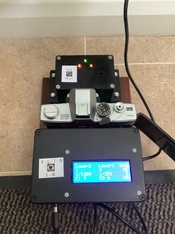
A new version of the shutter tester for Arduino NANO is ready :surprised:)
Ver 3_1_1

*** I would still suggest that new builds are done using the ESP32 (PM me for the code)
as there is far more functionality ***

For the Arduino version, which most people have built, the changes are:-

1) Milliseconds are now displayed to one decimal place, rather than a rounded integer.
(This removes the rounding that could display 552uS and 1mS, as shown on post #355)

2) Seconds are now displayed to two or three decimal places, rather than a rounded integer.

3) Curtain travel time is now displayed to one decimal place.

4) Laser alignment utility is now included. (Yay)

How use Laser alignment utility:-

The optional buttons, as detailed in post #150 must be added.

When first powering up, wait for the splash screen to display. Then press & hold the 'Display Average' button (wired to pin 12)
This jumps to the Laser alignment utility. Now release the button.

When the laser shines onto the receiver '**seen**' will be displayed on the LCD. If the receiver is not seeing the laser, 'blocked' will be displayed.
Each laser is shown independently.

There are two versions of the receivers (just to complicate things). This is why there are two versions of the code 'ori' (original) and 'new'
Receivers recently purchased are likely to be the 'new' type, so if you are not sure of what receivers you have, try using the 'new' code first.

If your lasers seem to be working backwards (when Laser is shining on the receiver, LCD says 'blocked') then you should try the over version of the code.

Due to absolutely no memory left, the only way to exit the laser alignment check, is to re-boot the tester.
Similarly, although I tried to include a software solution for the new & original laser receiver types in one build, it is not possible
due to memory space within the Arduino Nano. In the ESP32 version, this has been incorporated, as well as other functionality & for new builds or upgrades, I would suggest using an ESP32 board.

*** I would still suggest that new builds are done using the ESP32 (PM me for the code) as there is far more functionality ***


Code will now be stored on github. link below.

The code will now be a hex file. All fully assembled, making it simpler, as no additional libraries need to be added to Arduino IDE program.
Arduino IDE is still used for output to the computer screen.

To load onto your Arduino, first follow the link to the github site.

click on the green <>Code button, which will allow you to download all of the files as a zip file.
Un-zip the downloaded file. You will find two versions of Arduino code. 'ori' for the older original laser receivers and 'new' for the newer type.
(note:- there will also be an ESP32 version of the code, do not try loading this into an Arduino!).

To load the code onto the Arduino, you will need to download AVRDUDESS

follow the youtube video, from 2.30 to 5.15. Saravanan explains this, far better than I, how to use AVRDUDESS to load the code onto the Arduino.


github is a work in progress, so will be adding hardware build guides, general operation guides, loading software guides etc in the future.
Hope it is ok to take the build photos from Photrio & put them in the guides?

As always, appreciate a comment and photo of your finished shutter testers :surprised:)
 
OP
OP

Niglyn

Member
Joined
Feb 26, 2022
Messages
402
Location
Surrey, UK
Format
Analog
Adding a calibration value for faster shutter speeds?

Hi gang, we know that the shutter slot narrows as 'speeds' get faster and this causes an increasing error in the 'shutter speed' due to the curtain slot & laser beam width ratio getting smaller.

The secrets of how a professional shutter tester addresses this problem will remain a secret to us, we can only surmise, what, if anything they do. How is a professional shutter tester calibrated? Again they must have the same issue of the sensors having finite width?

We then have the problem of how to measure, even using an oscilloscope, as I have done, we still have the same issue of the sensor having width to its on/off point.

The next problem is curtain slot width will be different for different cameras. For example many old cameras have a flash sync of 1/30s. Meaning for 1/60s, the slot width will be half the frame.
A camera with flash sync of 1/250s. 1/500s will be half the frame. So a simple adjustment based on shutter speed alone, would not work?

Am I over-thinking this? However results from users does show that the shutter tester under-reads as 'shutter speed' increases.
could it just be that these old cameras do have progressively slower shutter speeds? I'm sure when I tested my Canon T70 (which has an electronically timed shutter) it was ok. I do not have access to this at the moment, to re-test.

Modern test kit is often calibrated by giving it known values & the in between values are calculated internally. this is why you often see an IR port, on Fluke equipment, for example. In this way the tester is not even opened. It is put into calibration mode, IR communication is used to say 'I'm sending you 10 Volts, I'm sending you 20 Volts' etc.

The alternate is to apply a calibration value, which is then multiplied as 'speed' increases. I'm open to mathematical formula for this.

Above are my rambling thoughts & musings. Hoping the hive mind will have comments, observations & suggestions.

Also happy for suggestions to add to the shutter-tester software. Thinking about adding recall averages on LCD and computer screen?
 

ic-racer

Member
Joined
Feb 25, 2007
Messages
16,483
Location
USA
Format
Multi Format
Whatever sensor/light combination people use, it needs to be checked against something.

I used all these:

Brand new Nikon f6
Electronic flash of known duration
Rotating focal plane shutter of known RPM and slit width

Also, on GitHub are two more that expand on two of the above.

One is a flashing LED. Though even that might need to be checked against something else to see how quickly the LED illuminates and extinguishes:


The next one is a rotating focal plane shutter that is adjustable with fixed RPM. Mine was not fixed RPM but I read the exact RPM off the output and adjusted my readings accordingly.


ic-racer

Member
Joined
Feb 25, 2007
Messages
16,483
Location
USA
Format
Multi Format
In terms of an analog professional tester, I can share some pictures of a Rollei EZKM tester. It displays the amount of charge of a capacitor. The capacitor is charged when the sensor is exposed to light, and the duration of light exposure is the shutter speed.
As you can see the slits are very thin. I don't think there is anything in the circuit to compensate for the physical width of the slit, but the device is only good up to 1/1000 of a second.


Meter small.jpg
35mm adapter shutter tester.jpg
Ezkm adapter 35mm small.jpg
Rollei EZKM smaller.jpg
 

ic-racer

Member
Joined
Feb 25, 2007
Messages
16,483
Location
USA
Format
Multi Format
ISO 516 on shutter speed testing outlines the sources of error based on slit width as follows.
Screen Shot 2023-09-07 at 11.38.05 AM.png
 

ic-racer

Member
Joined
Feb 25, 2007
Messages
16,483
Location
USA
Format
Multi Format
This is how the tester would be constructed according to ISO 516. There is a diffuser behind each slit. However, the next part indicates the sensors need to be adjusted in their output to only fire after 1/2 of the slit is exposed. The entrance slit needs to be less than the shutter curtain slit to be measured.
For many vintage cameras the smallest shutter curtain width would be 2.25mm.

Screen Shot 2023-09-07 at 11.46.03 AM.png


Screen Shot 2023-09-07 at 11.48.39 AM.png
 

ic-racer

Member
Joined
Feb 25, 2007
Messages
16,483
Location
USA
Format
Multi Format
My point with these posts is that the professional testers did not use laser light and ISO does not specify laser light. So, when using a laser, one needs to experiment to find out what one's high speed errors are and adjust accordingly.
 
Last edited:
OP
OP

Niglyn

Member
Joined
Feb 26, 2022
Messages
402
Location
Surrey, UK
Format
Analog
Hi ic,

Nice vintage shutter tester. Using capacitor charge to measure value is stone age technology :surprised:)
Thanks for posting the info. have also been reading

It seems the issue is well known & it is a case of living with it, there is no (easy) solution.
The problem arises at higher 'speed' or correctly narrower slit width, due to the sensor also having width.

Measuring w in post 346 would not be possible for the same reason.

As you posted in the other thread, calibration is easily done with a known slot width, but as the two curtains are not indexed, again, we are back to the same issue.

Also, whilst a camera with flash sync at 1/30s would have a slot width of half at 1/60, quarter at 1/120 etc, a camera with different flash sync speed would have different slot widths for each 'speed'

My thoughts are the following
a) it is a known issue with all testers, so accept the faster shutter 'speeds' will always read low, don't worry about it.
b) use the curtain speed, which should not be affected by sensor width, to add a calibration value as the two sensors 'seen' time is used for this measurement, thus does not have the same measuring issue.

Will post much of the above on the other thread, as that seems the best place for it, rather than having to threads exploring the same issue :surprised:)

In the mean time, as I do not have a workshop, or even a drill, would anybody like to volunteer to make a mask with the teeniest hole possible, to see how small a hole we can use to mask the sensor? The smaller the mast, the more accuracy will be achieved as speeds increase.

Similarly, in b) above, would anybody like to try some code with calibration applied for 32mm sensor spacing? Again I only have my prototype without masks and with random spacing, so cannot undertake any experimentation with hardware at the moment.
 
Last edited:

Twotone

Member
Joined
Mar 20, 2023
Messages
166
Location
UK
Format
Multi Format
Good evening Niglyn et al,

I've decided to take this on and see where it takes me. My gut feeling tells me this will be a nice challenge as is, given my electronics ability is relatively low already! If this gives me nice, usable readings up to 1/500th, then great, up to 1/1000th? Even better!

My intention is to use the main fundamentals, parts and coding from this but some of the 3d printed elements such as the sensor holder for the film plane from ic-racers build of the more complex GitHub shutter tester project.

I've seen one of the build PDFs of yours on GitHub talk about the masking the rx with 0.8mm holes (something I know has been spoken about in this thread recently).

For the sensor boxes I'm thinking of one with the rx 32mm apart for horizontal and then 20mm for vertical. I'd probably have a detachable sensor option as I assume these would require two different sensor options/switchable to achieve the functionality given the space limitations that has been pointed out on this thread.

I'm going to get everything ordered tonight based on the esp32 option.

I'm probably going to mount this on a nice bit of wood I bought for a shelf many moons back as my first prototype, and then review down the line.

Our pms will likely crossover timings with this thread but posting here so people can learn from my mistakes 😂

Thanks
TT
 
Photrio.com contains affiliate links to products. We may receive a commission for purchases made through these links.
To read our full affiliate disclosure statement please click Here.

PHOTRIO PARTNERS EQUALLY FUNDING OUR COMMUNITY:


Ilford ADOX Freestyle Photographic Stearman Press Weldon Color Lab Blue Moon Camera & Machine
Top Bottom