


Nimbus62
Subscriber
oups.. I change the credentials. Now will be fine for everybody.
About your failure in automatic mode, check connectivity or Tr12 (pin 4 and 5 from top circuit) to the control board C2 and S4.
it is not used in manual mode.
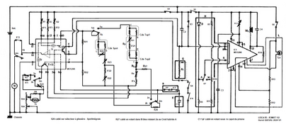
I added the picture of the top ceramic board with wire connection to the Leica add-on (pot, switch, bottom cell)
For your information, the ceramic board is a Minolta XE board where they cut 3 connection (see red lines).
I am working on a Service manual for LEaica R3 but have no time at the moment. I am working on Minolta XM project.
Last point: to adjust the cell response, have to adjust first Cds Spot as describe for XE with R23=RL R22=RS then adjust CLC Cds cell. What is not clear is the way to adjust R21 (RP) at the moment do not change/adjust R21. The most important is
1) to use clean and lubricated pot for Rsv and Rav. I use "Deoxit Fade Lub" with cotton buds. Do not spay directly!!!
2) to adjust correctly the current generator R1 and R2.
About your failure in automatic mode, check connectivity or Tr12 (pin 4 and 5 from top circuit) to the control board C2 and S4.
it is not used in manual mode.
I added the picture of the top ceramic board with wire connection to the Leica add-on (pot, switch, bottom cell)
For your information, the ceramic board is a Minolta XE board where they cut 3 connection (see red lines).
I am working on a Service manual for LEaica R3 but have no time at the moment. I am working on Minolta XM project.
Last point: to adjust the cell response, have to adjust first Cds Spot as describe for XE with R23=RL R22=RS then adjust CLC Cds cell. What is not clear is the way to adjust R21 (RP) at the moment do not change/adjust R21. The most important is
1) to use clean and lubricated pot for Rsv and Rav. I use "Deoxit Fade Lub" with cotton buds. Do not spay directly!!!
2) to adjust correctly the current generator R1 and R2.

 . I believe that what i circled is S7 and check the wires of PCB1 pin 4&5. At some point i though, maybe there is just dirt somewhere, so i sprayed it with isopropyl alcohol a little and blew it dry. Then the auto mode fired fast, but B and X got stuck when fired. Now i'm back to square one. Firing at mechanical speed at all speeds... I'm getting a bit done with this one. When i got the camera, this was the same problem. Firing at 'x' at all speeds except 'B'. Then i managed to take the front partially off and clean the magnets with a toothpick with isopropyl, and the manual speeds worked since then. But now it's all mechanical again. To take the front off was already such a hassle and a miracle i managed to put it back together that i'm doubting if i want to try that again. I'm almost considering asking if i can send it to you in France


