TPrins
Member
Hi Nimbus, Andreas and Tprins,I have been following this thread with interest. My R3 was a mess when I got it. Manual 500 and 1000 were too fast: fiddling with R12 solved that. On automatic speeds were way too slow and getting slower after a few tries. So, on reading all the useful information I started cleaning pots and switches. That didn't help: manual speeds were okay, but automatic speeds too slow ( up to10s of seconds! ). I decided to replace capacitor C1 ( 2,2 uF 16 v ) and automatic times are now normal ( they need adjustment, but automatic behaviour is consistent.) . The original capacitor C1 (beige one under PCB-A ) was faulty.
Another thing I found out when working on this camera was that the spot/average switch can be pushed too far forward when the bodywork is off. The result is that the camera starts behaving: suddenly automatic speeds are too slow ( 10 or more seconds). So keep an eye on this switch when testing.
Interesting!!!
Currently i feel a little lost. I picked it up again to work on the steps Nimbus wrote and suddenly the mirror would stay up after firing. Turns out some wires on top disconnected, so after fixing that i'm suddenly back on track.
- manual times seem to work okay now. 4s is very close to 4s
- automatic times are still up to 10s like you had too.
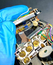
- C1 looks pretty bad to me. I've got a spare body with water damage, that i could take the C1 of. (2nd photo) Maybe i can measure first if C1 is the problem? How? i got a basic multimeter.
- Since you live in NL too, i'm secretly wondering if you're interested in me shipping or bringing you the body to have a go at it.
- also wondering how you are able to check the manual 500 and 1000 speeds. Do you have a shutter tester?
- Nimbus says, C2 could also be the problem. Is that the flat brown one under the shutter lever?
Thanks for all the involvement in this guys.